 3D ROOM
 (0)
(0) English
 عربى
عربى
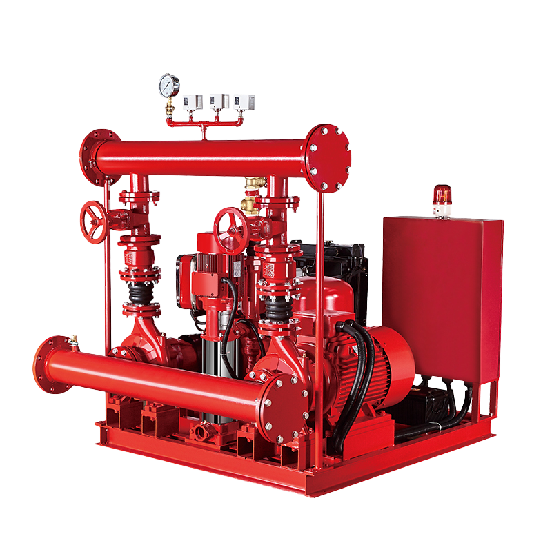 Fire Pump and System
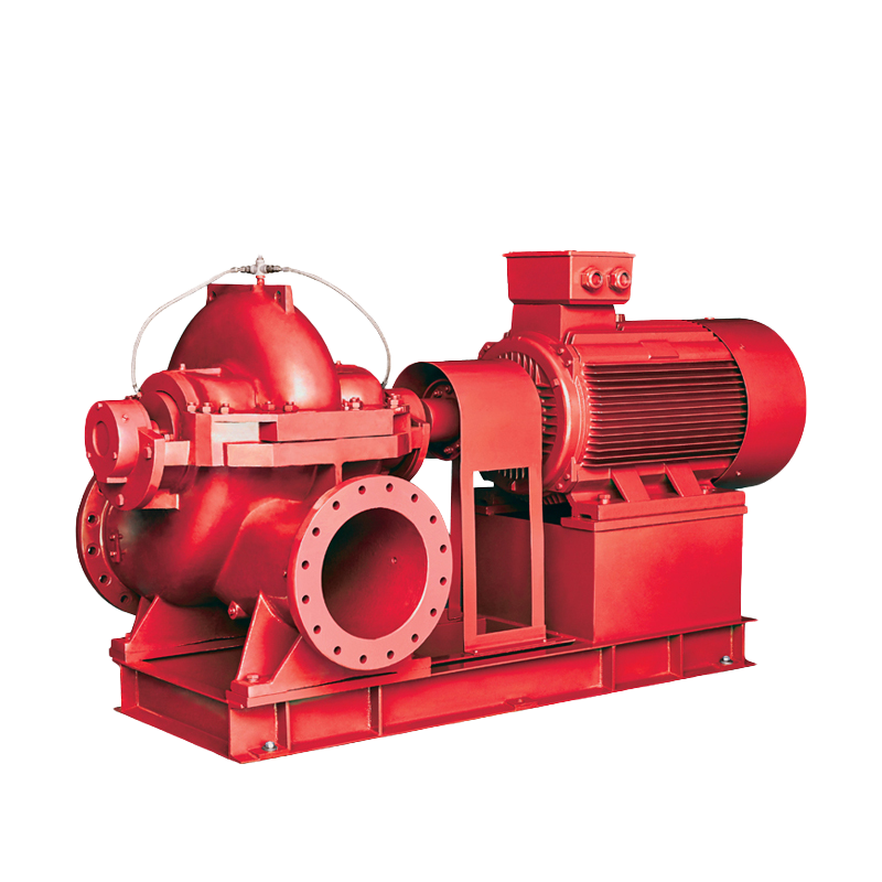 Split Case Pump
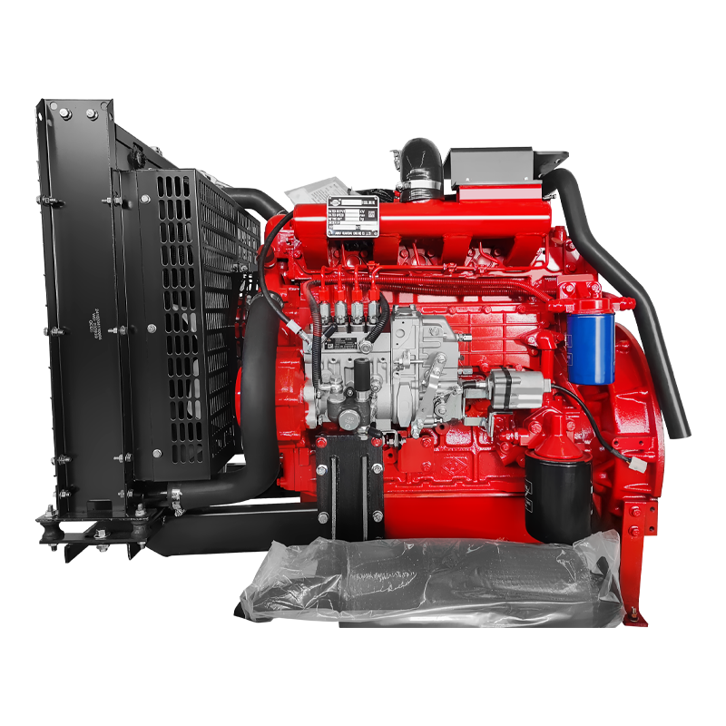 Engine and Pump
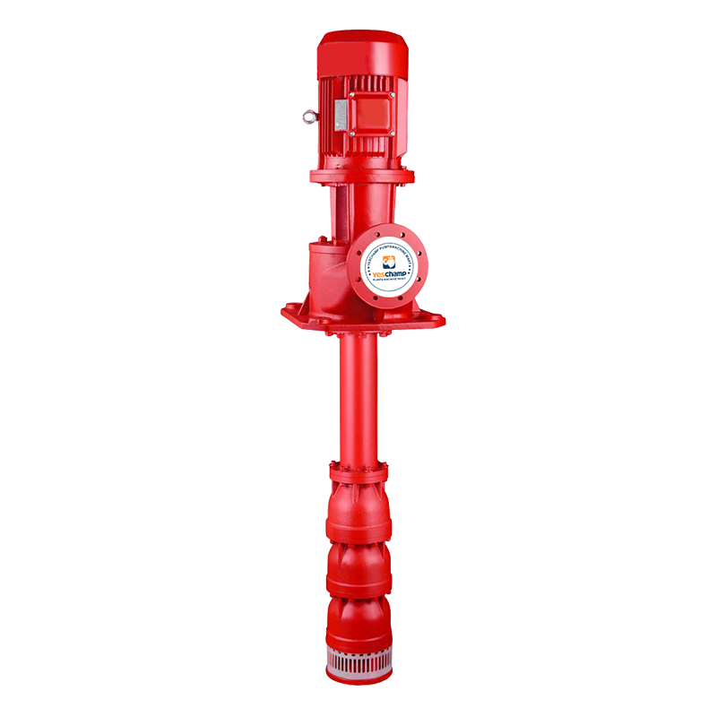 Long Shaft Pump
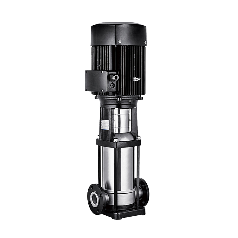 Multistage pump
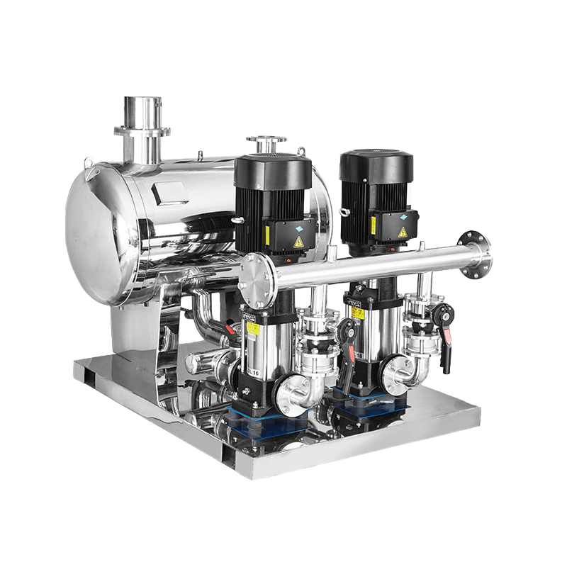 Water Supplier System
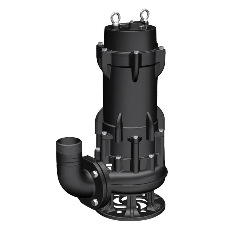 Sewage Pump
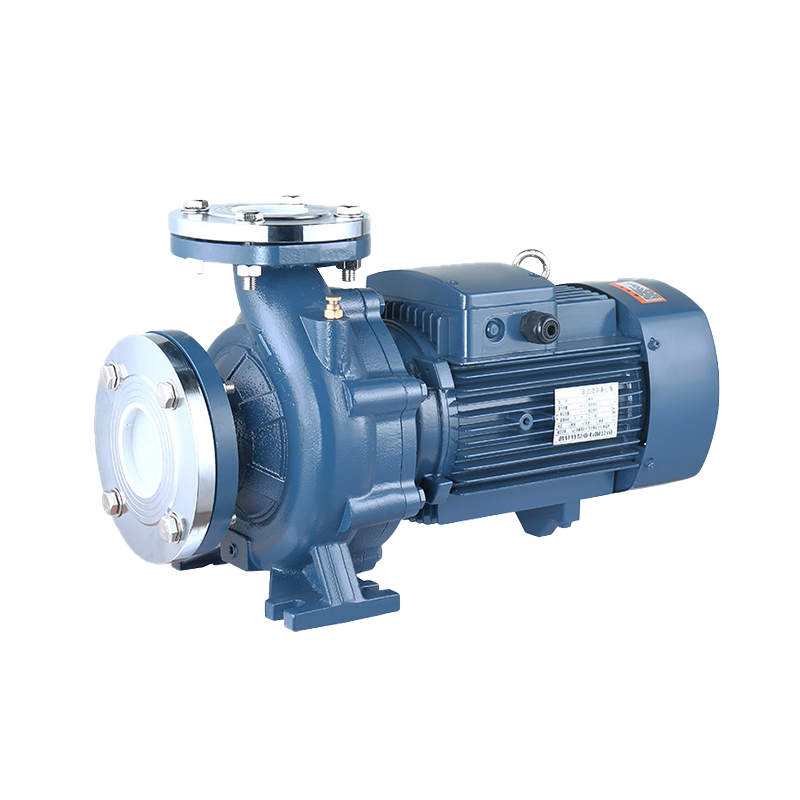 Industrial Pump
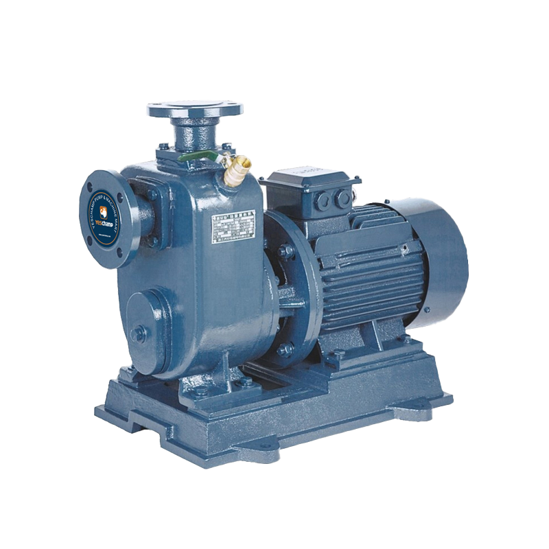 Self-Priming Pump
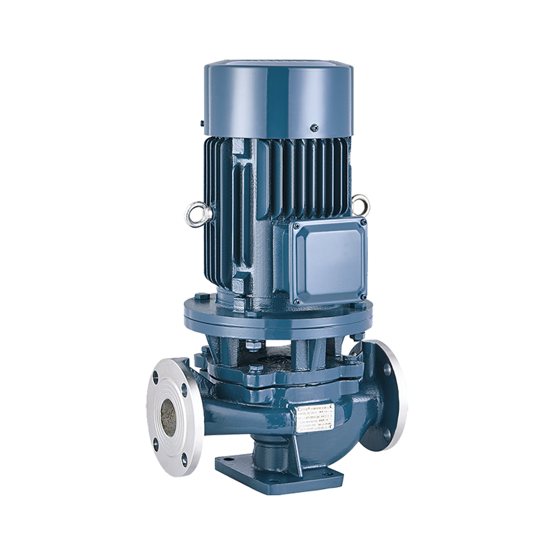 Inline Pump
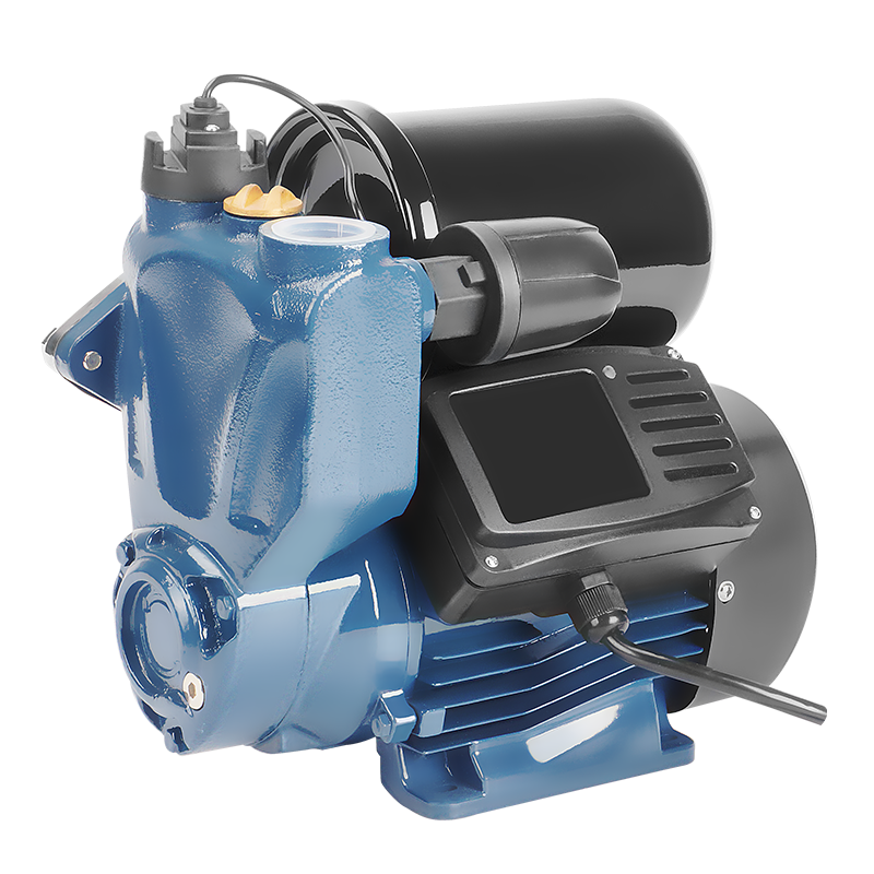 Domestic Pump
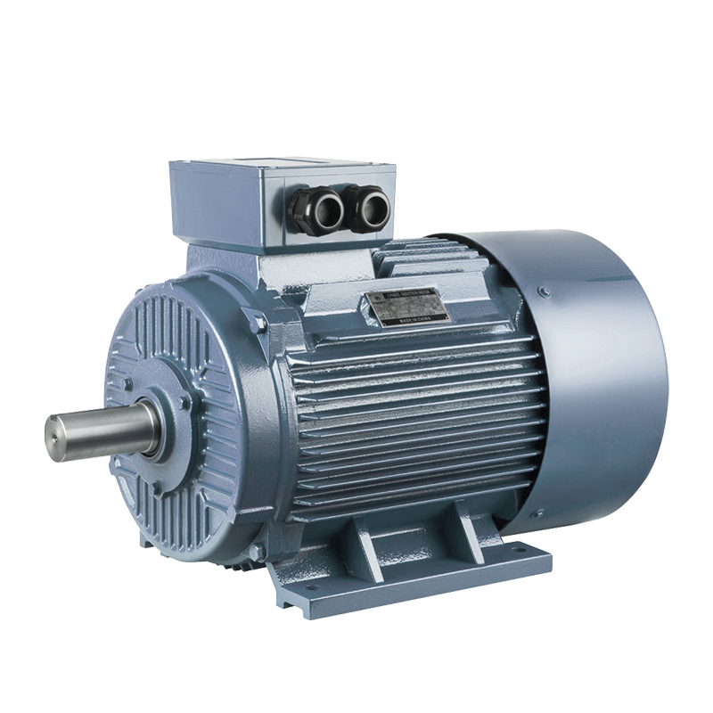 Electric Motor
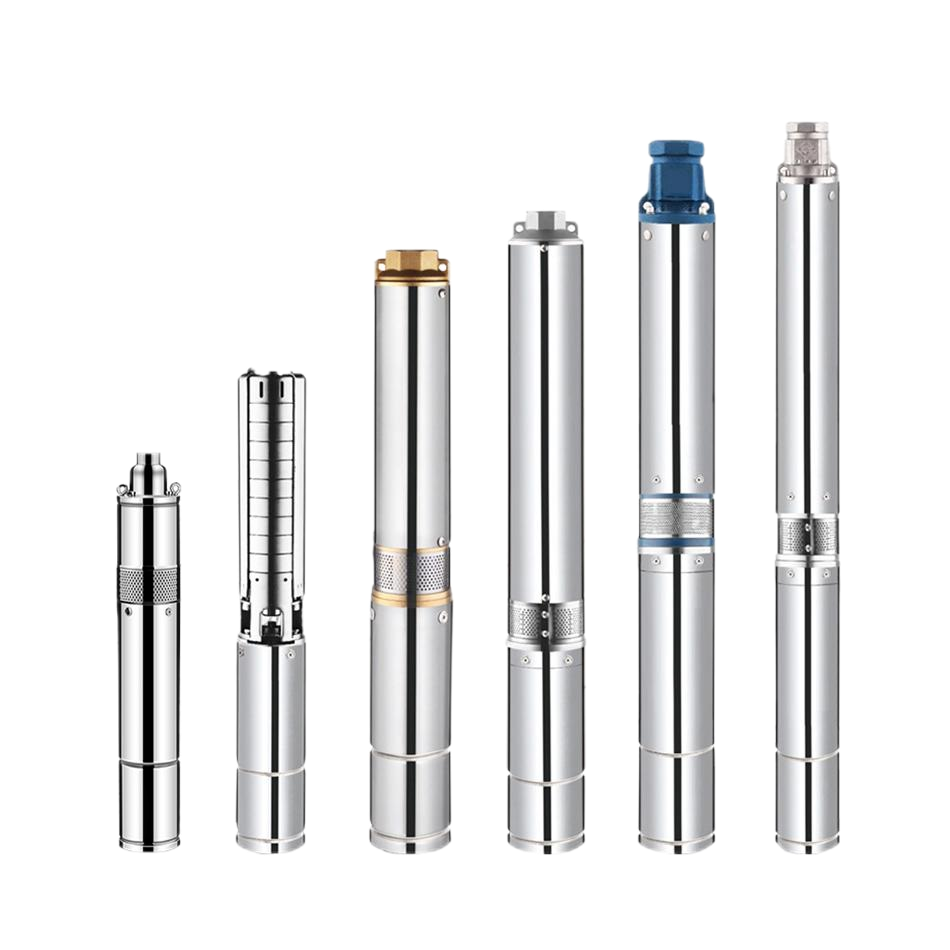 Borehole Pump
In fire protection engineering, the Electric Pump + Diesel Pump + Jockey Pump (Multistage) configuration is widely recognized as the ultimate triple-redundant fire pump system.
Required by international building codes for commercial high-rises, industrial complexes, and critical infrastructure, this setup ensures that pressurized water is delivered to sprinklers and hydrants under any emergency scenario—even during total power grid failure.
Here is a comprehensive, search-optimized guide covering the system architecture, operating logic, and specification criteria for this system.
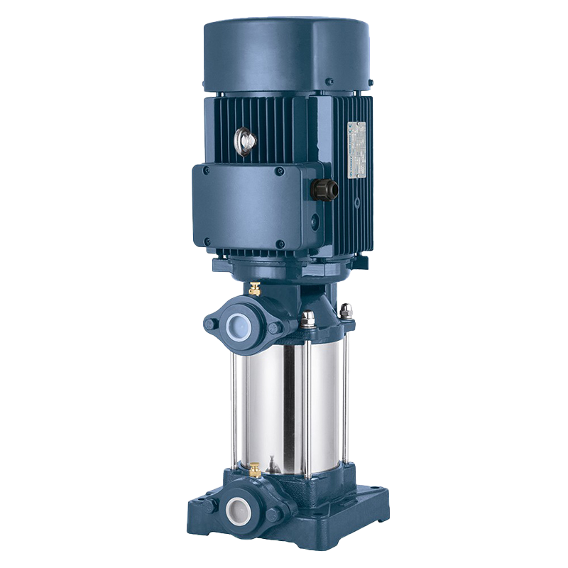
1. The Jockey Pump (Vertical Multistage Centrifugal)
-
Primary Role: Pressure maintenance & leak compensation.
-
Operation: Small capacity ($1\%\text{ to }3\%$ of main fire flow, typically 5–30 GPM), high head. It automatically turns on when minor pressure drops occur (due to thermal expansion or small fitting leaks) and shuts off once standard static pressure is restored.
-
Why Multistage? Vertical multistage pumps (with SS304 or PPO impellers) generate high pressure with a compact vertical footprint, preventing the main pumps from starting unnecessarily.
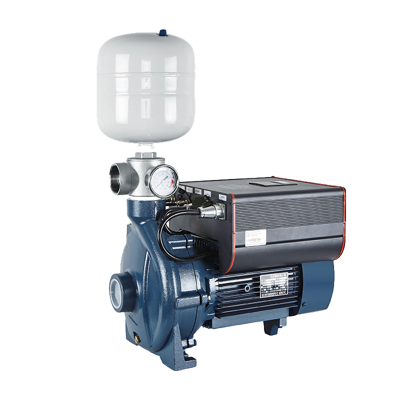
2. The Primary Fire Pump (Electric Motor Driven)
-
Primary Role: Main emergency fire suppression.
-
Operation: Sized for $100\%$ of the required system flow ($Q$) and Total Dynamic Head ($H$). When a fire sprinkler opens or a hydrant valve is thrown, line pressure drops rapidly past the jockey pump's threshold, triggering the electric fire controller to start the primary electric pump.
-
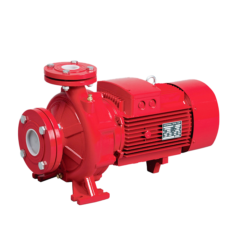
Pump Styles: Horizontal Split-Case, End Suction, or Vertical Turbine.
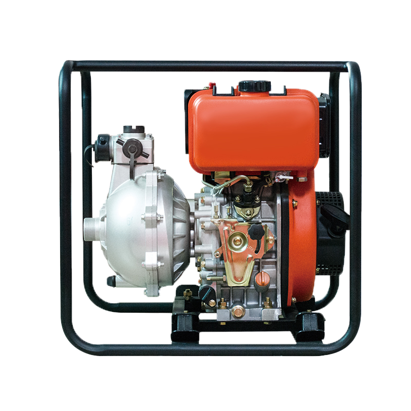
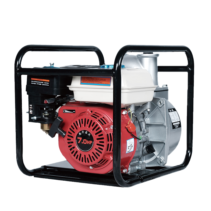
3. The Secondary Fire Pump (Diesel Engine Driven)
-
Primary Role: 100% emergency backup during power outages.
-
Operation: Fires frequently cause electrical short circuits or grid shutdowns. If the electric pump fails to start or loses power, system pressure drops further to the tertiary setpoint, engaging the diesel engine driver. The diesel unit operates completely independently using an on-site fuel tank and dual 24V cranking batteries.
2. Pressure Switch Cascade & Automatic Logic
To prevent simultaneous starting and ensure seamless takeover, the system uses a cascading pressure switch logic:
Static System Pressure (e.g., 120 PSI)
   │
   ├── Drop to 110 PSI ──► [Jockey Pump STARTS] (Restores back to 120 PSI, then stops)
   │
   ├── Drop to 95 PSI  ──► [Electric Fire Pump STARTS] (Requires manual or timed stop)
   │
   └── Drop to 80 PSI  ──► [Diesel Fire Pump STARTS] (Failsafe backup / Power outage)
Note on NFPA 20 Rules: While jockey pumps start and stop automatically based on pressure, main fire pumps (Electric and Diesel) are required to start automatically but must be stopped manually (or via a strict minimum run timer) to ensure fire ground personnel maintain full control during an incident.
3. Technical Comparison Matrix
| Feature / Parameter | Jockey Pump | Main Electric Fire Pump | Main Diesel Fire Pump |
| Pump Type | Vertical Multistage (PPO/SS) | End Suction / Split Case | End Suction / Split Case |
| Flow Capacity ($Q$) | Low ($5 - 30\text{ GPM}$) | Full ($500 - 5,000+\text{ GPM}$) | Full ($500 - 5,000+\text{ GPM}$) |
| Driver Power | 3-Phase Electric Motor | High-kW Electric Motor | Compression-Ignition Diesel Engine |
| Power Source | Mains Power | Primary Building Grid / Genset | Dedicated Fuel Tank + Cranking Battery |
| NFPA Standard | Covered under NFPA 20 | NFPA 20 / UL Listed / FM Approved | NFPA 20 / UL Listed / FM Approved |
4. Key Accessories in a Packaged Skid
When procuring an integrated Electric + Diesel + Jockey fire pump package, the entire skid is usually factory-assembled with:
-
Fire Pump Controllers: Separate NEMA-rated control cabinets for the electric driver, diesel driver, and jockey pump.
-
Suction & Discharge Headers: Common manifolds equipped with OS&Y gate valves, butterfly check valves, and pressure relief valves.
-
Flow Meter Loop & Hose Header: Installed for annual NFPA 25 flow testing (50%, 100%, and 150% capacity points).
-
Fuel System & Battery Racks: Double-wall fuel tank sized for at least 8 hours of continuous full-load diesel operation.
 5th Floor, Comprehensive Building No. 5, Dongqiao, Dong'an Village, Daxi Town,Wenling City,Zhejiang,China
 +86 576 86090666
 +86 18667600006
 +86 18667600006
 24 Hours Online