 3D ROOM
 (0)
 English
 عربى

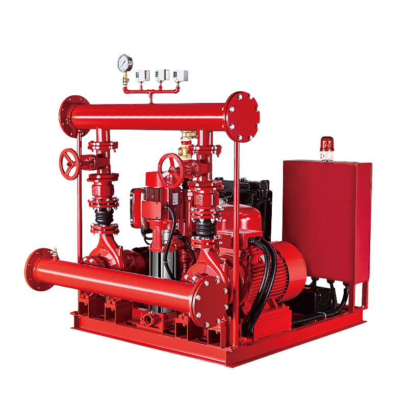 Fire Pump and System
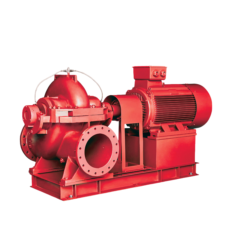 Split Case Pump
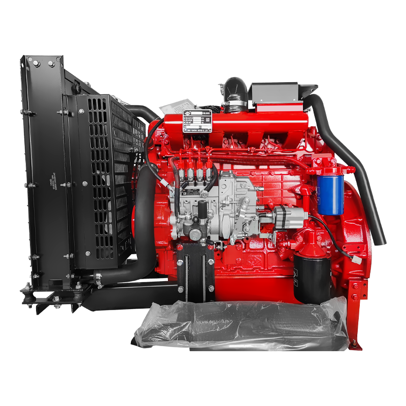 Engine and Pump
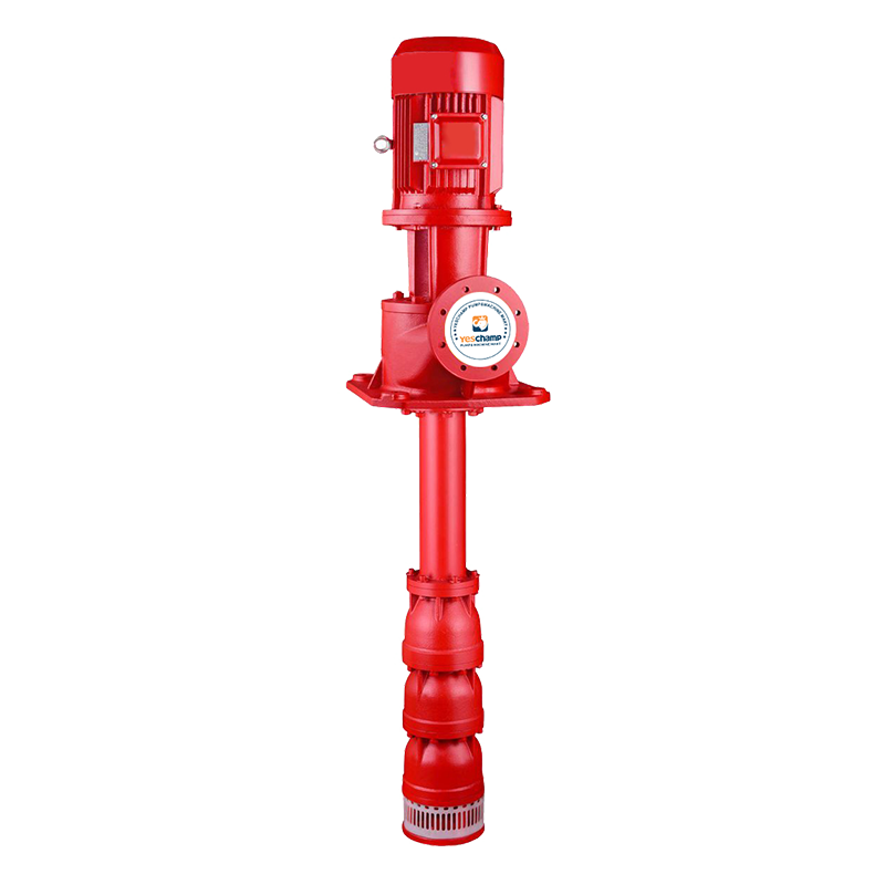 Long Shaft Pump
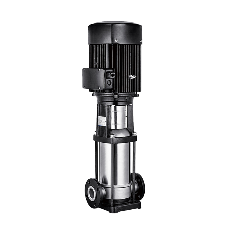 Multistage pump
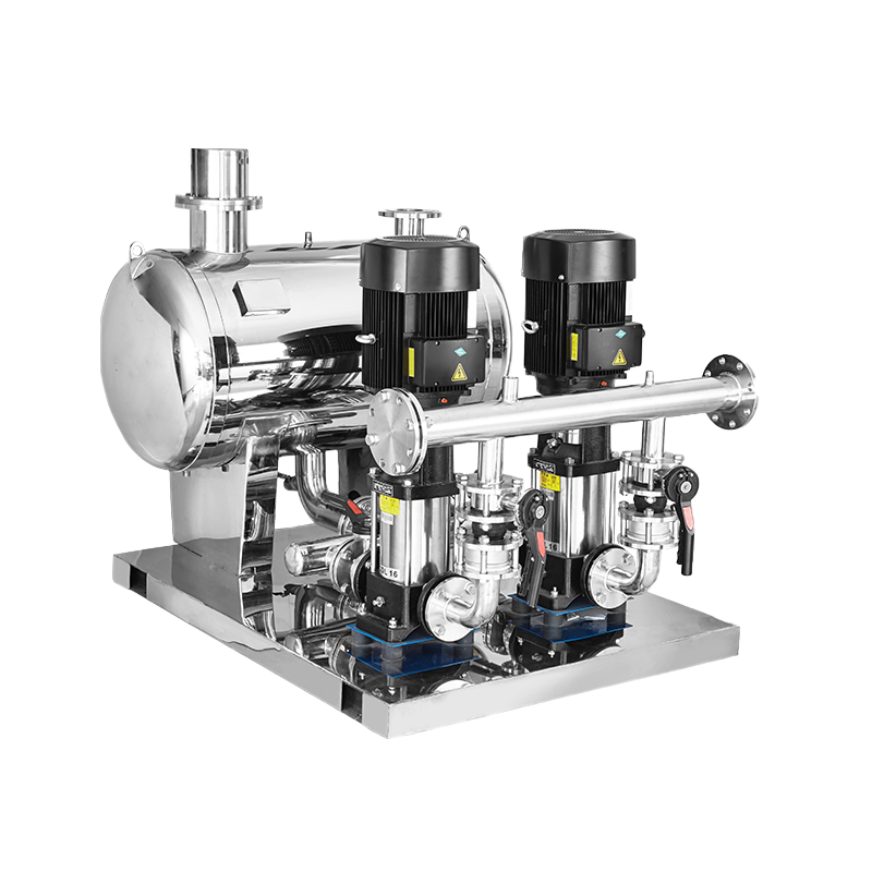 Water Supplier System
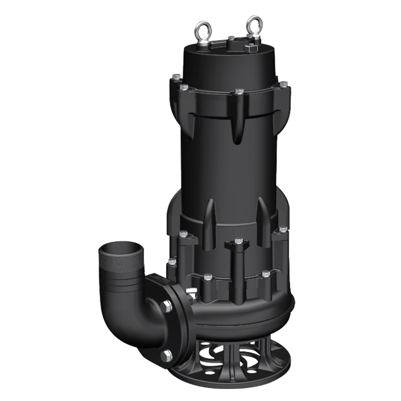 Sewage Pump
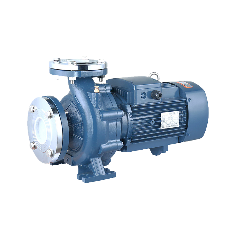 Industrial Pump
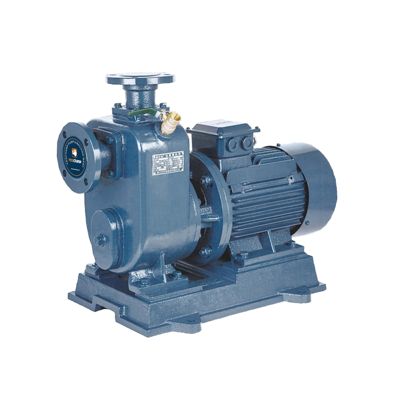 Self-Priming Pump
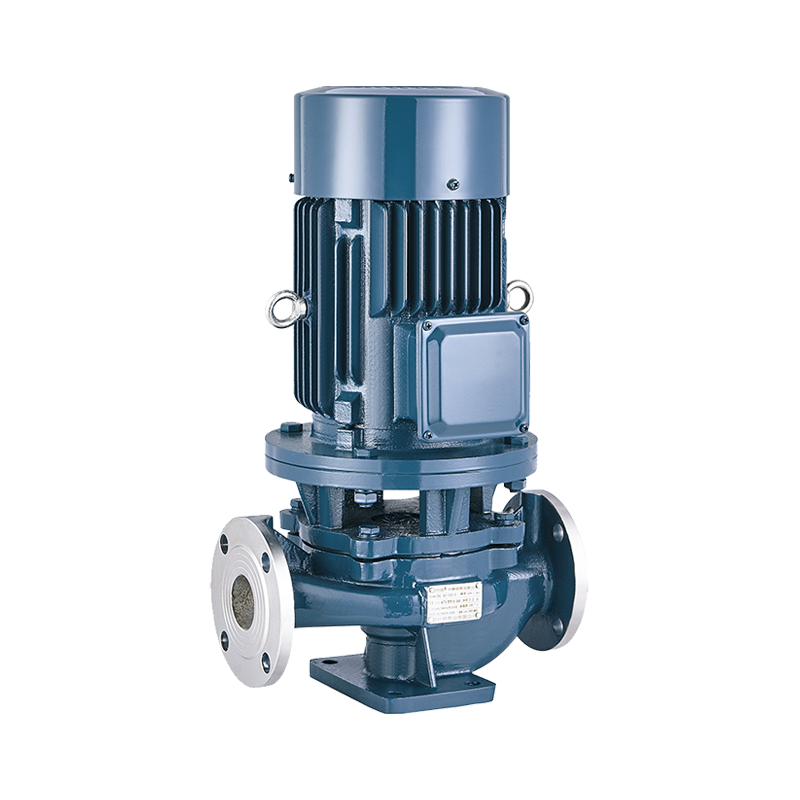 Inline Pump
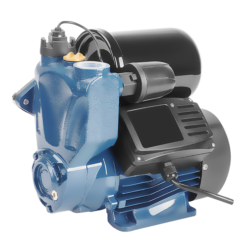 Domestic Pump
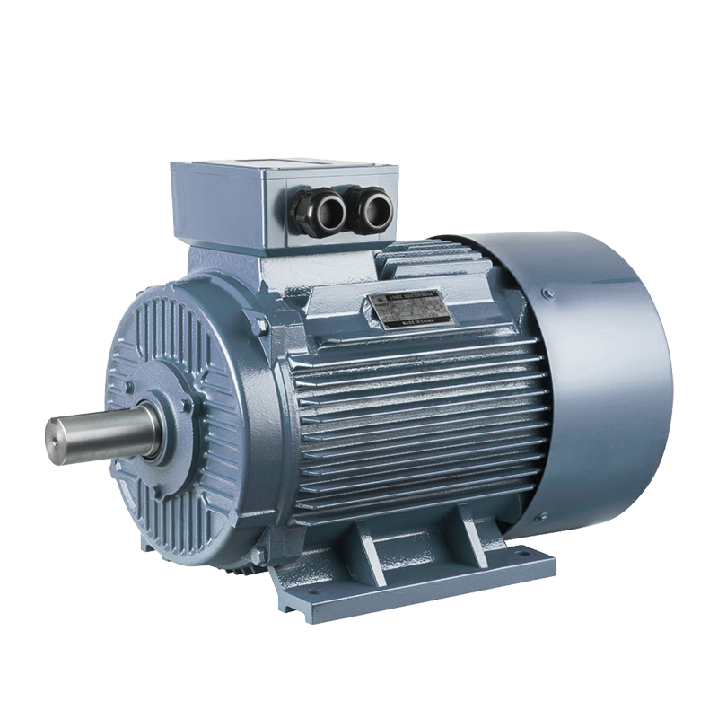 Electric Motor
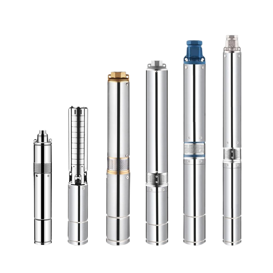 Borehole Pump
Vertical Turbine Fire Pump (Long Shaft Fire Pump): Selection, Installation, and Maintenance Guide
A vertical turbine fire pump, also known as a long shaft fire pump in many project specifications, is designed to supply reliable fire water from a deep tank, reservoir, well, or other water source where a horizontal pump cannot maintain suitable suction conditions. Its bowl assembly and impellers are installed below the water level, while the vertical drive shaft connects the pump to a driver located above the discharge head. This arrangement allows the pump to lift water from a deep source and deliver the pressure and flow required by a fire protection system.
A long shaft fire pump is not selected by motor power or discharge size alone. The designer must evaluate the required fire flow, total head, water level, suction conditions, shaft length, pump bowl arrangement, driver type, discharge piping, foundation, and fire pump control system. This guide explains the construction, operating principle, applications, selection criteria, installation requirements, commissioning process, maintenance practices, and common troubleshooting points for a vertical turbine fire pump system.What Is a Vertical Turbine Fire Pump?
A vertical turbine fire pump is a vertical-shaft centrifugal pump with one or more impellers installed in submerged bowl assemblies. The pump bowls are positioned below the minimum water level so that the impellers remain flooded and ready to deliver water. A vertical discharge head at the top of the pump supports the shaft, guides the flow into the discharge connection, and provides the interface between the pump and its driver.
The driver may be an electric motor or a diesel engine connected through a vertical right-angle gear drive, depending on the project design. The driver turns the long vertical shaft, which rotates the impellers inside the submerged bowls. Each impeller adds energy to the water, and the bowl passages convert velocity into pressure as the water moves upward through the pump column.
The phrase “long shaft fire pump” describes the extended vertical shaft arrangement used to transmit power from the above-ground driver to the submerged pump assembly. It is commonly used when the water source is deep or when the pump must be installed above the water source for access, ventilation, and maintenance. Exact terminology can vary between manufacturers and project documents, so the complete pump construction and performance data should always be checked.
How Does a Long Shaft Fire Pump Work?
When the fire pump receives a start signal, the driver rotates the vertical shaft. The shaft transfers torque through the column to the impellers in the bowl assembly. Water enters the lowest impeller through the suction opening and is accelerated outward by centrifugal force. The bowl or diffuser then converts part of the velocity energy into pressure energy and guides the water to the next stage.
A multistage vertical turbine pump uses several impellers to build higher pressure. The water passes through each stage in sequence until it reaches the discharge head. A single-stage design may be sufficient for a lower head requirement, while a multistage arrangement is used when the fire protection network needs greater pressure. The number of stages, impeller diameter, rotational speed, and bowl dimensions determine the pump performance.
Because the pump bowls are submerged, the pump does not depend on a long suction line to lift water into a dry-installed casing. This can be a major advantage when the water level varies or when the source is located below the pump room. However, the minimum submergence, water quality, shaft alignment, column assembly, and water-lubricated or product-lubricated bearings must be properly designed and maintained.
Vertical Shaft and Bowl Assembly
The long shaft is normally supported by bearings installed at intervals along the column. The shaft, couplings, column pipe, bearings, and bowl assembly must be manufactured and aligned as a complete system. Excessive shaft deflection, incorrect coupling installation, damaged bearings, or poor foundation alignment can produce vibration and premature wear.
The bowl assembly may include suction bell, impeller, diffuser bowl, wear rings, shaft, and intermediate components. The materials should be selected for the water quality and expected service conditions. Sand, corrosion, and suspended solids can affect impeller clearances, wear rings, bearings, and bowl surfaces, so the water source must be reviewed before final design.
Where Are Vertical Turbine Fire Pumps Used?
Vertical turbine fire pumps are used when the available fire water source is below the pump discharge elevation or when a flooded suction arrangement is difficult to achieve with a horizontal fire pump. Common applications include deep fire water tanks, underground reservoirs, open storage tanks, lakes, rivers, wells, industrial fire water basins, and municipal water sources with changing water levels.
They are frequently installed in industrial plants, power facilities, warehouses, refineries, chemical facilities, airports, high-rise developments, and large commercial sites. These projects may require high fire flow and reliable operation even when the water source is far below the pump room. A vertical turbine configuration can place the driver and controls in an accessible above-ground location while keeping the hydraulic pump components below the water level.
The pump may also be selected where the water source has a variable operating level. The pump bowls can be positioned at a suitable depth, allowing the impellers to remain submerged at the minimum design water level. The designer must still verify the lowest water level, vortex risk, submergence, inlet velocity, and available water volume during the full fire demand period.
A vertical turbine fire pump is not automatically suitable for every open water source. Water containing excessive sand, debris, algae, corrosive chemicals, or biological growth may require screening, special materials, additional maintenance, or a different pump arrangement. The water intake and pump suction design should be considered together to reduce the risk of blockage and wear.
Main Components of a Vertical Turbine Fire Pump System
The submerged pump assembly is the hydraulic core of the system. It normally includes the suction bell, bowl or diffuser stages, impellers, wear rings, shaft, bearings, and bowl connections. The assembly is selected to meet the required fire flow and pressure at the specified speed. The hydraulic components must remain below the minimum water level and be supported by the column and foundation system.
The column assembly contains the vertical shaft, column pipe, shaft couplings, and line-shaft bearings. Its purpose is to transfer power from the driver to the bowls and to guide the shaft during operation. Shaft length and bearing spacing are important design factors. The assembly must be rigid enough to control deflection and accurately aligned during installation.
The discharge head supports the driver or gear drive and directs water from the column into the discharge pipe. It may include a stuffing box, mechanical seal, shaft enclosure, pressure gauge connections, and mounting surfaces. The discharge head must be securely anchored and connected to pipework without imposing excessive external loads on the pump.
The driver can be an electric motor or a diesel engine with a right-angle gear drive. An electric driver requires a suitable fire pump controller, reliable power supply, grounding, and protection systems. A diesel driver requires a fuel tank, batteries, charger, cooling system, exhaust arrangement, ventilation, and engine controller. In both cases, the driver must provide sufficient power at the actual pump duty and environmental conditions.
The system also includes discharge valves, check valves, test connections, pressure gauges, sensing lines, flow measurement equipment, and monitoring devices. Every valve and control component must be installed according to the approved design, clearly identified, accessible, and protected from accidental closure or damage.
Advantages and Limitations of a Long Shaft Fire Pump
The main advantage of a vertical turbine fire pump is its ability to draw water from a deep source while keeping the driver and major controls above ground. The submerged bowl assembly provides flooded suction conditions and can reduce the limitations associated with suction lift. This makes the design suitable for reservoirs and tanks where the water level is significantly below the pump room.
Another advantage is the ability to produce high flow and pressure through multiple stages in a relatively compact footprint. The vertical layout can save floor space compared with some horizontal pump arrangements. It also allows the hydraulic pump components to be placed at a depth that supports reliable water entry during the required fire duration.
The limitations are mainly related to installation complexity, alignment, access, and inspection. A long shaft and multiple column sections require careful assembly and accurate alignment. Removing the bowl assembly or shaft may require lifting equipment and sufficient vertical clearance. The water source must be clean enough to limit wear, and the pump cannot be assessed only by looking at the above-ground driver.
A vertical turbine pump can also have more demanding commissioning requirements than a compact horizontal pump. Shaft rotation, bearing lubrication, coupling fit, column alignment, submergence, and driver settings must all be verified. A technically correct pump can still perform poorly if the foundation, intake, water level, or discharge pipework is incorrect.
How to Select a Vertical Turbine Fire Pump
Selection begins with the hydraulic demand of the fire protection system. Determine the required flow rate and pressure at the design point, including sprinkler demand, hydrant demand, hose station demand, deluge systems, elevation, pipeline friction, valves, fittings, and required residual pressure. The pump should be selected from a complete certified or approved performance curve that matches the project requirements.
Next, establish the water-source conditions. Record the maximum, normal, and minimum water levels; reservoir dimensions; intake arrangement; water temperature; water quality; and the expected duration of fire pump operation. The lowest water level is especially important because the impellers must remain sufficiently submerged and the suction bell must operate without excessive vortex formation or air entrainment.
The pump bowl and stage arrangement should then be selected to provide the required head at the specified flow. The designer should check shutoff pressure, rated pressure, driver power, speed, efficiency, NPSH-related conditions, shaft length, bearing arrangement, and maximum allowable operating limits. If the water contains sand or suspended solids, the impeller, wear rings, bearings, and bowl materials may need special consideration.
Finally, choose the driver and control system. Confirm whether the project requires an electric motor, diesel engine, or another approved arrangement. Review the power supply, starting method, right-angle gear drive, fuel system, ventilation, exhaust, ambient temperature, altitude, and controller functions. The driver and pump should be supplied and tested as a matched set whenever possible.
Vertical Turbine Fire Pump Selection Checklist
Installation Requirements for a Vertical Turbine Fire Pump
The foundation must be designed to support the total pump and driver load while maintaining accurate alignment. Anchor bolts, soleplates, baseplates, and discharge-head supports should be installed according to the approved foundation drawing. The foundation should be level, rigid, and capable of resisting operating vibration. The vertical clearance above the pump must be sufficient for installing and removing shaft sections, column components, and the bowl assembly.
Before installation, inspect every component for transport damage and verify part numbers, shaft sections, couplings, bearings, column pipes, bowl stages, fasteners, and seals. Keep machined surfaces clean and protected. Confirm the assembly sequence before lowering components into the well, tank, or pump pit. Dirt, incorrect coupling orientation, or a damaged bearing can create problems that are difficult to diagnose after the pump is fully assembled.
The bowl assembly must be installed at the correct elevation and remain below the minimum water level. The suction bell should have sufficient clearance from the tank bottom and surrounding walls. The intake should be protected from large debris, excessive turbulence, and vortex formation. Follow the manufacturer’s requirements for minimum submergence and intake velocity.
Column sections should be lowered and connected carefully. Each shaft coupling must be correctly fitted, tightened, and checked for proper end play and rotation. Line-shaft bearings must be installed in the specified positions. The column should remain vertical as it is assembled, and any deviation should be corrected before the discharge head and driver are installed.
The discharge pipe must be independently supported so that its weight and thermal or mechanical loads are not transferred to the discharge head. Install check valves, isolation valves, pressure gauges, and test connections according to the design. Ensure that pressure-sensing lines are correctly connected and free from blockage. Before startup, flush the discharge system and remove construction debris from the water source and pipework.
Commissioning and Testing a Long Shaft Fire Pump
Commissioning begins with a document and installation review. Confirm that the installed pump, driver, gear drive, controller, valves, water source, and test equipment match the approved design. Check that the foundation, anchor bolts, discharge connections, protective guards, lubrication points, fuel system, batteries, and electrical connections are complete.
Verify the water level and ensure that the bowl assembly and suction bell are fully submerged at the test condition. Check that the intake is clear and that the water source has sufficient volume for the planned performance test. Confirm that all discharge valves are positioned correctly and that the test route can safely handle the expected flow and pressure.
Before starting the driver, manually inspect the shaft and coupling assembly according to the manufacturer’s procedure. Verify the direction of rotation, shaft lubrication, bearing condition, gear-drive oil, engine fluid levels, battery condition, or motor insulation as applicable. Make sure the pressure-sensing line and controller start signal operate correctly.
Start the pump and observe shaft movement, vibration, noise, discharge pressure, flow, driver speed, and bearing or gear-drive temperature. Test the pump at appropriate flow points and compare the results with the performance curve. Record suction or water-level conditions, discharge pressure, flow, driver current or fuel condition, and alarm indications.
After testing, return valves and controls to the normal standby position. Confirm that the pump can receive an automatic start signal and that all alarms and supervisory signals are transmitted correctly. Prepare a commissioning report containing measured data, test conditions, observed issues, corrective actions, and final operating settings.
Maintenance of a Vertical Turbine Fire Pump
A vertical turbine fire pump should be kept in a ready-to-operate condition even when it is not running. Routine inspections should include the driver, gear drive, discharge head, shaft enclosure, bearings, valves, gauges, controller, water source, fuel system, and test equipment. The maintenance frequency should follow the manufacturer’s instructions, approved fire protection procedures, and applicable local requirements.
Inspect the water source for low level, floating debris, sediment, algae, corrosion, and intake blockage. The reservoir or tank should be kept clean enough to prevent material from entering the suction bell. Check that the minimum water level remains compatible with the bowl depth and required fire duration. Any change in water level, intake condition, or source quality should be evaluated before the pump is needed.
For the mechanical assembly, check for abnormal vibration, shaft movement, leakage at the discharge head, worn packing or seal components, loose fasteners, bearing problems, and unusual noise. Inspect column and shaft components during planned shutdowns. If the pump has water-lubricated bearings, confirm that the specified lubrication conditions are present before operation.
For an electric driver, inspect motor terminals, grounding, controller indicators, starting equipment, insulation condition, and cooling. For a diesel driver, inspect fuel quality, battery voltage, charger status, engine oil, coolant, belts, hoses, exhaust, ventilation, and alarms. The right-angle gear drive should be checked for oil level, leakage, temperature, vibration, and abnormal sound.
Maintain detailed service records. Record inspection dates, water levels, test flow, discharge pressure, driver readings, vibration observations, alarm events, repairs, spare parts, and changes to controller settings. Trend data helps identify developing shaft, bearing, hydraulic, or driver problems before they cause a loss of fire pump availability.
Common Vertical Turbine Fire Pump Problems and Troubleshooting
If the pump fails to deliver the required flow or pressure, check the water level, suction bell, intake blockage, valve position, shaft rotation, impeller condition, stage arrangement, and discharge resistance. A low water level or blocked intake can restrict the pump even when the driver is operating normally. Compare measured data with the performance curve and verify that the pump is operating at the specified speed.
Excessive vibration may be caused by shaft misalignment, incorrect coupling installation, bent shaft sections, worn line-shaft bearings, loose foundation bolts, pipe strain, damaged impellers, or a problem in the gear drive. Stop the pump when safe, inspect the above-ground components, and arrange a detailed mechanical inspection if the vibration continues. Do not assume that vibration from a long shaft is normal.
Unusual noise can indicate cavitation-like conditions, insufficient submergence, vortex formation, air entrainment, damaged bearings, insufficient lubrication, foreign material, or gear-drive wear. Check water level, intake conditions, bearing lubrication, and driver alignment. The pump should be operated within the manufacturer’s permitted flow and speed range.
If the driver overloads or trips, check excessive flow, high liquid density, mechanical friction, bearing damage, shaft misalignment, incorrect motor settings, low voltage, phase imbalance, fuel-system problems, or engine alarms. Repeatedly resetting electrical or engine protection without identifying the cause can damage the equipment and reduce system reliability.
If the pump starts unexpectedly or fails to start automatically, inspect the pressure-sensing line, controller settings, fire system pressure, start signal, battery or power supply, and manual stop condition. A leaking fire protection network may cause repeated starts, while a blocked sensing line may delay the start signal. All control changes should be made by authorized personnel and documented after testing.
Energy Efficiency and Life-Cycle Cost
Fire pumps are emergency equipment, so reliability and compliance are more important than minimizing energy use at the expense of performance. Even so, the pump should be correctly sized and should operate efficiently at its required duty point. An oversized pump can create excessive pressure, increase test losses, and place additional mechanical stress on valves and pipework. An undersized pump may not deliver the required fire flow or residual pressure.
Life-cycle cost includes the pump and driver purchase price, foundation and installation work, test equipment, energy or fuel use, inspection labor, spare parts, water-source maintenance, and the cost of unplanned downtime. A long shaft pump with reliable bearings, accessible replacement parts, accurate documentation, and responsive technical support may offer better long-term value than a cheaper pump with unclear materials or incomplete service information.
During procurement, request the performance curve, driver input data, efficiency information where applicable, shaft and bearing details, water-quality limits, maintenance requirements, spare-parts list, and recommended test procedure. Comparing complete life-cycle information helps the project team select a system that is reliable, serviceable, and suitable for the actual fire protection duty.
Conclusion: Choosing a Vertical Turbine Long Shaft Fire Pump
A vertical turbine fire pump, often called a long shaft fire pump, is an effective solution when fire water must be lifted from a deep tank, reservoir, well, or other source below the pump room. Its submerged bowl assembly provides flooded suction conditions, while the vertical shaft transfers power from an electric motor or diesel engine above the water source. This design can deliver high flow and pressure in demanding industrial, commercial, and infrastructure fire protection systems.
The correct choice depends on the complete hydraulic and mechanical design. Confirm fire flow, total head, minimum water level, bowl submergence, intake conditions, shaft length, water quality, driver type, foundation, discharge piping, control system, test arrangement, and maintenance access. Before ordering, request complete performance curves, dimensional drawings, material information, shaft and bearing data, driver specifications, installation instructions, test requirements, spare-parts recommendations, and warranty terms. A detailed technical review helps prevent low flow, vibration, cavitation, alignment problems, delayed starting, and costly emergency repairs.
Vertical Turbine Fire Pump FAQ
What is a vertical turbine fire pump?
A vertical turbine fire pump is a vertical-shaft centrifugal fire pump with submerged bowl assemblies and impellers installed below the water level. An electric motor or diesel engine above the water source drives the impellers through a vertical shaft. It is commonly used when the water source is deep or when a horizontal pump cannot maintain suitable suction conditions.
Is a vertical turbine fire pump the same as a long shaft fire pump?
In many project specifications, “long shaft fire pump” refers to the vertical shaft arrangement used by a vertical turbine pump. The exact terminology can vary between manufacturers and standards. Buyers should confirm the bowl assembly, shaft construction, driver arrangement, performance curve, and installation requirements rather than relying on the name alone.
Where is a vertical turbine fire pump used?
It is used for deep fire water tanks, underground reservoirs, wells, industrial fire water basins, open storage tanks, lakes, rivers, and other sources located below the pump room. It is suitable for facilities that require reliable fire flow while keeping the driver and controls accessible above ground.
How deep can a long shaft fire pump be installed?
The allowable depth depends on the pump model, shaft design, column length, bearing arrangement, water level, bowl construction, driver, and manufacturer’s limits. The pump must maintain adequate submergence and shaft stability at the minimum water level. Request a manufacturer-approved dimensional and performance design for the actual installation depth.
What is the difference between a vertical turbine pump and a horizontal fire pump?
A vertical turbine pump has submerged bowls and a vertical shaft, while a horizontal fire pump normally has the pump and driver installed at floor level with a different suction arrangement. A vertical turbine pump is often selected for deep or variable-level water sources. A horizontal pump may be simpler to access when suitable flooded suction and installation space are available.
Does a vertical turbine fire pump require a diesel engine?
Not always. The pump may be driven by an electric motor or by a diesel engine with a vertical or right-angle drive arrangement, depending on the project design, power availability, and applicable fire protection requirements. The selected driver must provide adequate power and reliable starting for the complete pump duty.
How is a vertical turbine fire pump maintained?
Maintenance includes checking water levels, intake conditions, valves, discharge pressure, flow, shaft vibration, bearings, couplings, discharge-head seals, driver condition, gear-drive oil, controllers, and test equipment. Electric drivers require electrical and insulation checks, while diesel drivers require fuel, battery, coolant, exhaust, and engine inspections. Keep complete service and performance records.
Suggested Internal-Link Anchors: vertical turbine pump selection guide, diesel fire pump system, fire pump room requirements, fire pump testing procedure, long shaft pump maintenance, industrial fire protection system
Primary CTA: If you are sourcing a vertical turbine fire pump or long shaft fire pump, prepare the required fire flow, total head, minimum water level, source dimensions, shaft depth, driver type, and installation layout, then request a complete performance curve and technical proposal from a qualified fire pump supplier.
 5th Floor, Comprehensive Building No. 5, Dongqiao, Dong'an Village, Daxi Town,Wenling City,Zhejiang,China
 +86 576 86090666

 +86 18667600006
 +86 18667600006
 24 Hours Online
