 3D ROOM
 (0)
 English
 عربى

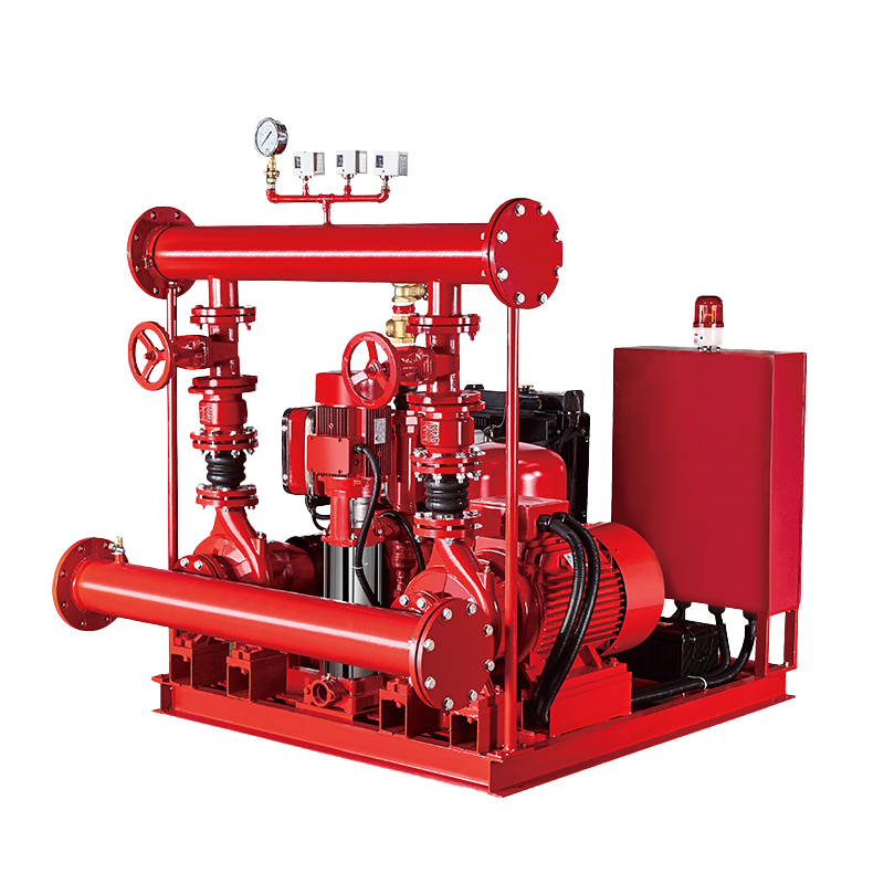 Fire Pump and System
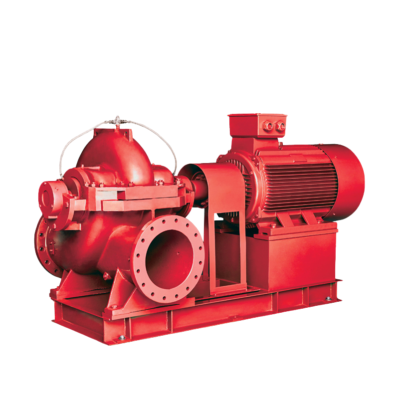 Split Case Pump
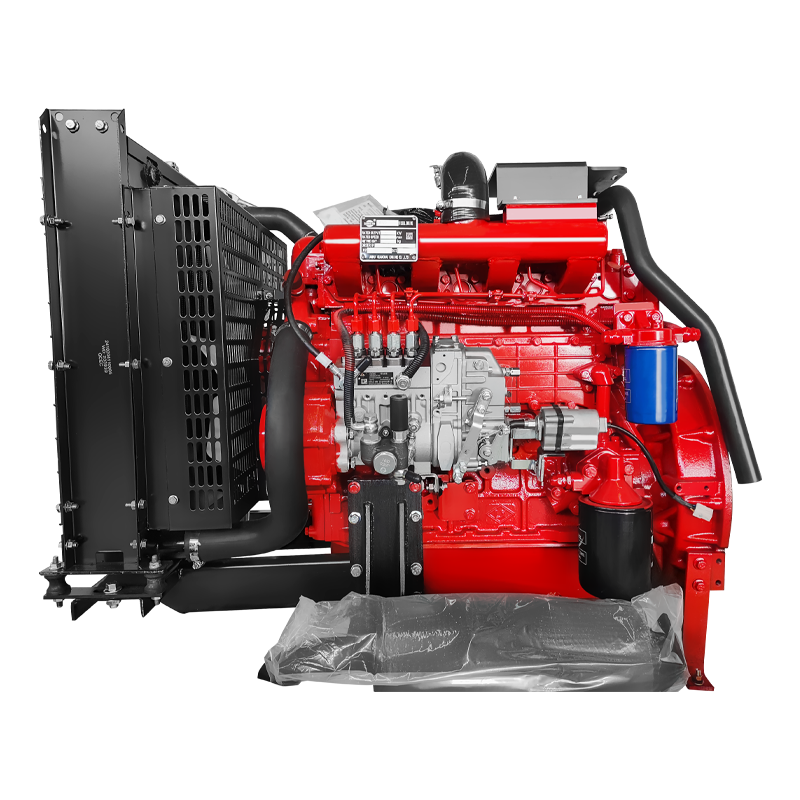 Engine and Pump
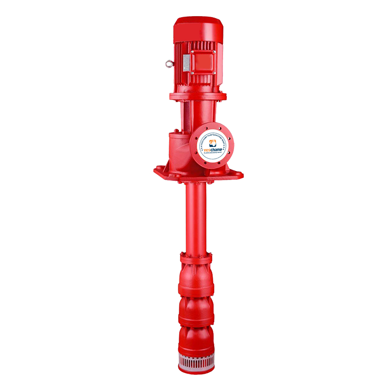 Long Shaft Pump
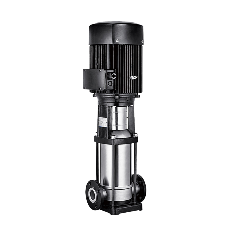 Multistage pump
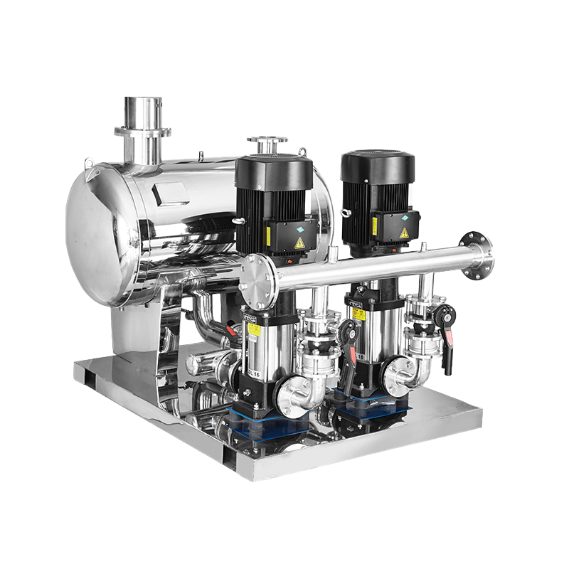 Water Supplier System
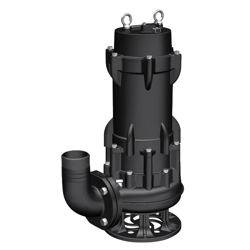 Sewage Pump
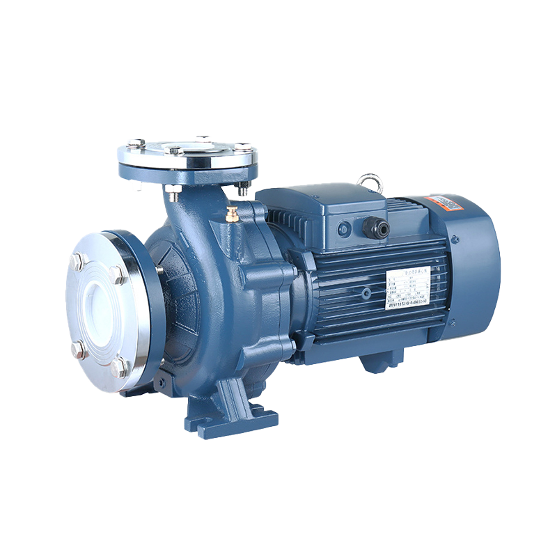 Industrial Pump
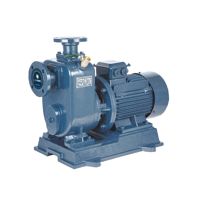 Self-Priming Pump
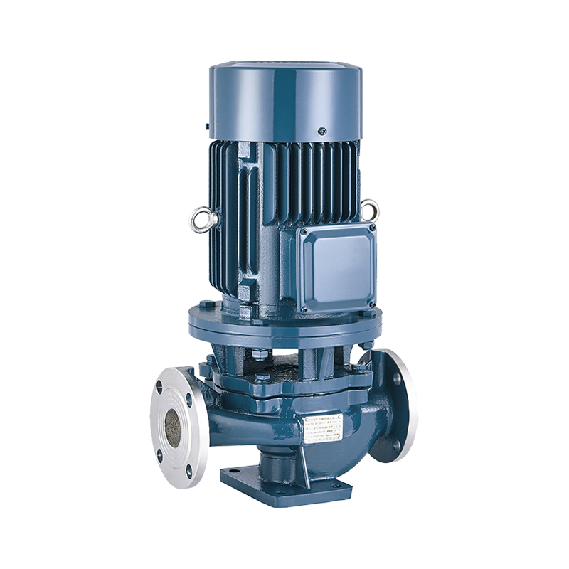 Inline Pump
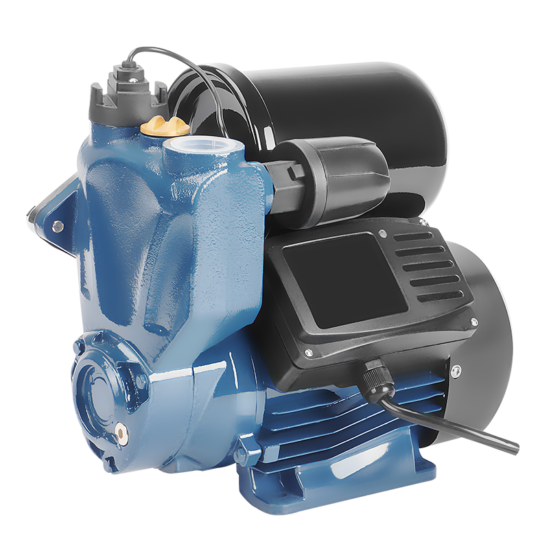 Domestic Pump
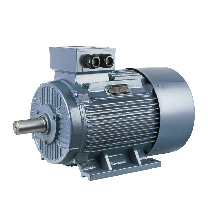 Electric Motor
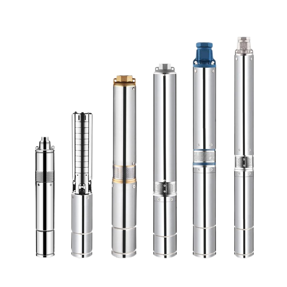 Borehole Pump
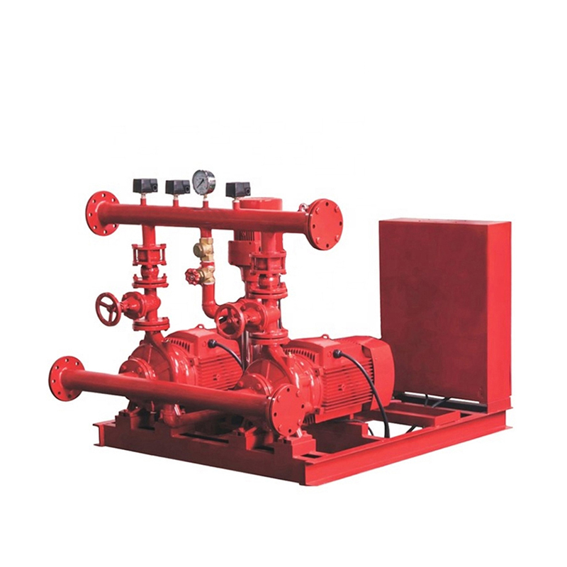
Fire Pump System with Multistage Electric Pump and Multistage Diesel Pump
A fire pump system with a multistage electric pump and a multistage diesel pump is designed to provide reliable fire water pressure and flow under both normal and emergency power conditions. The multistage electric fire pump can serve as the main duty pump when dependable electrical power is available, while the multistage diesel fire pump provides an independent standby source when the electric pump cannot operate or when additional capacity is required. Because both pumps use multiple impellers arranged in series, the system can deliver high pressure in demanding sprinkler, hydrant, hose reel, deluge, and industrial fire protection networks.
This configuration requires more than installing two high-pressure pumps beside each other. The pump curves, start sequence, water source, suction conditions, controllers, valves, power supply, diesel fuel system, test arrangement, and pressure settings must work together. This guide explains the system architecture, operating sequence, component selection, installation, commissioning, maintenance, energy considerations, and common troubleshooting points for a multistage electric pump and multistage diesel pump fire protection system.
What Is a Multistage Electric and Diesel Fire Pump System?
A multistage electric and diesel fire pump system normally includes a multistage electric fire pump, a multistage diesel fire pump, pump controllers, pressure-sensing lines, suction and discharge manifolds, isolation valves, check valves, pressure gauges, test connections, and a reliable water source. Depending on the project, it may also include a jockey pump, pressure-maintenance tank, flow meter, automatic transfer equipment, diesel fuel tank, batteries, battery charger, ventilation, exhaust piping, and remote alarm interfaces.
Each multistage pump uses several impellers connected in series. Every stage adds energy to the water, allowing the pump to reach a higher total head than a comparable single-stage pump. The electric and diesel pumps may have similar hydraulic performance, or they may be arranged with different capacities according to the approved fire protection design. The exact relationship must be confirmed from the performance curves and system design rather than assumed from the pump names.
The electric pump is driven by an electric motor and controlled by an electric fire pump controller. The diesel pump is driven by a diesel engine and controlled by a diesel fire pump controller. The diesel unit normally includes batteries, chargers, a fuel tank, engine cooling, exhaust, ventilation, and monitoring devices. These support systems are essential because a diesel pump cannot provide reliable standby protection if it lacks fuel, battery power, cooling, or a safe starting environment.
A jockey pump may be installed with this arrangement to maintain normal system pressure during small leakage or temperature-related pressure changes. The jockey pump is not a replacement for either main fire pump. Its purpose is to prevent unnecessary starts of the multistage electric or diesel pump when there is no significant fire water demand.
How Does the Fire Pump System Work?
When the fire protection network is in standby condition, the pipes are filled with water and maintained at the required pressure. The pressure-sensing line monitors the system. If pressure drops slightly because of minor leakage or normal pressure fluctuation, the jockey pump starts and restores pressure. If the pressure drop continues or the system has no jockey pump, the configured main pump start sequence is activated.
The multistage electric pump usually starts when the pressure falls below its automatic start setting, provided that the electrical supply and controller are available. Once it starts, the series impellers build pressure and deliver water to the fire protection network. Depending on the approved control philosophy, the electric pump may remain running until manually stopped after the fire event or test. Automatic stopping and starting logic must follow the project requirements and applicable fire protection rules.
The multistage diesel pump starts when the pressure falls to its configured start point, when the electric pump is unavailable, or when the approved sequence calls for the standby pump to operate. The diesel controller energizes the starter, the engine accelerates, and the multistage pump supplies the network. In some systems, the diesel pump is a standby unit that starts after an electric-pump failure. In other systems, both pumps may be selected to meet a larger flow demand or provide operational redundancy.
The operating sequence must prevent unwanted simultaneous starts while ensuring that the required fire flow is available. Pressure settings, time delays, controller interlocks, power-failure signals, and manual controls should be confirmed during commissioning. Operators should not alter these settings without authorization, because an incorrect sequence can cause nuisance starts, delayed operation, or insufficient pressure.
Electric Pump and Diesel Pump Operating Roles
The electric pump generally provides the most convenient and energy-efficient operation when reliable power is available. The diesel pump provides independent driving power and can maintain fire protection capability during a utility power failure or electrical equipment problem. The two pumps should not be treated as automatically interchangeable: they must be matched to the approved system curve, duty point, driver capability, and control sequence.
Why Use Multistage Pumps in a Fire Protection System?
A multistage pump is suitable for fire protection systems that require high pressure at a defined flow rate. Instead of relying on one large impeller to produce all the pressure, the pump adds pressure progressively through multiple stages. This can support high-rise building systems, long pipe networks, industrial fire protection, high-elevation hydrants, deluge systems, and installations with significant friction or static head.
Using a multistage electric pump together with a multistage diesel pump can improve system resilience. The electric pump can handle the normal duty when the electrical infrastructure is reliable, while the diesel pump provides an independent backup. If the project requires multiple pumps to operate together, the hydraulic curves and control settings must be coordinated so that the combined flow and pressure are suitable for the network.
The configuration may also support maintenance planning. One pump can be available while the other is being inspected, provided that the remaining unit and water supply still meet the approved fire protection requirements. This benefit depends on the project design and should not be assumed. A standby pump that is not sized or approved for the full required duty may not provide adequate protection on its own.
Multistage pumps also have limitations. Their internal passages may be less tolerant of debris, sand, and contaminated water than those of certain large-passage pumps. They require correct suction conditions, protection against dry running, proper alignment, and careful stage inspection. The system designer must balance pressure requirements with water quality, maintenance access, spare-parts availability, and life-cycle cost.
Main Components of the Fire Pump System
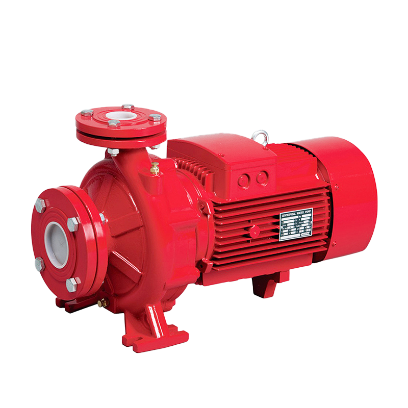
The multistage electric fire pump includes a centrifugal pump with multiple impellers, a vertical or horizontal pump arrangement depending on the model, an electric motor, coupling or drive assembly, base, mechanical seal, and electric controller. The motor and controller must be selected for the required pump power, starting current, voltage, frequency, and operating environment.
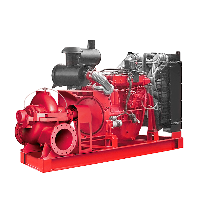
The multistage diesel fire pump includes a multistage centrifugal pump, diesel engine, coupling or right-angle gear drive where applicable, diesel controller, batteries, battery chargers, fuel tank, cooling system, exhaust system, and monitoring devices. The engine must provide sufficient power at the project altitude, ambient temperature, and ventilation conditions. Fuel piping and the tank must be protected from contamination, leakage, overheating, and accidental damage.
The suction manifold supplies water to the pump inlets. It should provide stable flow and avoid excessive friction, air pockets, turbulence, or unequal flow distribution. The discharge manifold combines or routes pump discharge according to the design and normally includes check valves, isolation valves, pressure gauges, test connections, and flow measurement equipment.
The controllers manage automatic start signals, manual operation, alarms, monitoring, and status indication. The electric controller may monitor power availability, motor overload, phase loss, and controller faults. The diesel controller may monitor battery voltage, charger status, engine speed, low fuel, overspeed, low oil pressure, high coolant temperature, and failure to start.
The water source may be a dedicated fire water tank, reservoir, municipal connection, or other approved supply. Its capacity and replenishment rate must support the required fire duration and pump flow. A high-capacity pump set cannot compensate for an inadequate water source, blocked intake, or insufficient suction pressure.
How to Select Multistage Electric and Diesel Fire Pumps
Selection begins with the hydraulic design of the fire protection network. Determine the required flow and pressure at the most demanding design point, including sprinkler demand, hydrant demand, hose stations, deluge equipment, elevation, pipe friction, valves, fittings, and residual pressure. Select each pump from a complete performance curve at the actual duty point. Do not select a pump only by motor horsepower, number of stages, or discharge diameter.
The electric and diesel pumps should be compared at the same design conditions. Confirm rated flow, rated head, shutoff pressure, operating pressure, efficiency, impeller diameter, rotational speed, driver power, and allowable operating range. If one pump is intended as standby, confirm whether it must match the full capacity of the duty pump or whether the approved design permits a different duty arrangement.
Check the suction conditions carefully. Confirm the water level, available suction pressure, NPSH-related requirements, suction-pipe size, intake condition, and risk of air entering the pump. A high-pressure multistage pump can experience noise, vibration, cavitation, and reduced flow if the suction side is restricted or the water source is too low.
The diesel pump selection must include environmental factors. Engine power may be affected by altitude, ambient temperature, ventilation, and exhaust backpressure. The fuel tank must provide the required operating reserve, while batteries and chargers must support repeated starting attempts. The electric pump selection must account for available power, transformer capacity, starting current, cable size, controller rating, and backup power strategy.
Fire Pump Selection Checklist
Installation Requirements for a Multistage Fire Pump System
The pump room must provide enough space for installation, operation, inspection, testing, and removal of the electric pump, diesel pump, controllers, valves, batteries, engine components, and other equipment. The foundation should be level, rigid, and capable of limiting vibration. Maintenance access routes should allow technicians to handle heavy motors, engines, couplings, and pump components safely.
Suction piping should be short and direct where practical, with appropriate pipe diameter and minimal unnecessary elbows. Pipe supports must carry the pipe weight and prevent external loads from being transferred to the pump casing or manifold. The suction system should be cleaned and flushed before startup to remove welding debris, scale, sand, and construction materials.
Install discharge piping, valves, check valves, pressure gauges, sensing lines, and test connections according to the approved design. Confirm the flow direction of check valves and the accessibility of all isolation valves. Pressure-sensing lines should accurately reflect the fire system pressure and should be protected against blockage, leakage, freezing, or mechanical damage.
The diesel pump room requires suitable ventilation and exhaust arrangements. The engine must receive sufficient combustion and cooling air, while exhaust gases must be discharged safely away from air intakes and occupied areas. The fuel system should be installed away from excessive heat and protected against leakage. Batteries and chargers should remain accessible and protected from moisture and accidental damage.
Electrical installation should include grounding, cable protection, controller connections, motor protection, alarm wiring, and verification of phase sequence. If an automatic transfer switch or emergency generator is used, its interface with the electric fire pump controller should be tested. The installation should not rely on undocumented field changes to achieve the intended operating sequence.
Commissioning and Testing Procedure
Commissioning begins with a document and visual inspection. Confirm that the electric pump, diesel pump, controllers, valves, water source, suction and discharge pipework, pressure gauges, flow meters, fuel tank, batteries, and test arrangements match the approved design. Remove temporary construction materials and ensure that all equipment is accessible.
Check mechanical readiness by inspecting couplings, guards, shaft alignment, lubrication, fasteners, seals, and pipe supports. Confirm that suction and discharge valves are correctly positioned and that the water source has sufficient volume. For the diesel unit, verify fuel level and quality, engine oil, coolant, batteries, chargers, exhaust, ventilation, and controller alarms.
Test the pressure-maintenance sequence if a jockey pump is installed. Simulate a small pressure loss and confirm that the jockey pump starts and stops correctly. Then simulate a larger pressure drop and verify the start signal to the multistage electric pump. Confirm electric motor rotation, starting current, discharge pressure, flow, alarms, and manual controls.
Test the diesel pump automatic start sequence by using the approved test method. Verify battery cranking, engine start, speed stability, discharge pressure, flow, fuel condition, abnormal alarms, failure-to-start signals, and manual operation. If the diesel pump is intended to start after an electric-pump failure, simulate the approved failure condition without compromising equipment safety.
Conduct hydraulic performance testing at suitable flow points and compare the results with the supplied pump curves and project requirements. Record suction pressure, discharge pressure, flow, motor current, engine speed, fuel condition, vibration, noise, and temperatures. After testing, restore the system to normal standby conditions and document all results, settings, defects, and corrective actions.
Maintenance of Electric and Diesel Multistage Fire Pumps
A fire pump system must remain ready even when it is not operating. Routine inspections should cover both pumps, controllers, valves, pressure gauges, sensing lines, water source, test equipment, and alarm interfaces. The maintenance schedule should follow the manufacturer’s instructions, approved fire protection procedures, and applicable local requirements.
For the electric pump, inspect motor terminals, grounding, controller indicators, insulation condition, cooling, coupling, mechanical seal, bearings, valves, and abnormal vibration. Check that the power supply is available and that protective devices do not show a fault. A loss of power, phase imbalance, incorrect setting, or damaged cable can prevent the pump from starting when required.
For the diesel pump, inspect fuel level and quality, battery voltage, charger status, engine oil, coolant, belts, hoses, exhaust, air filters, fuel lines, and visible leakage. Start the engine according to the approved test program and confirm that it reaches stable speed. Keep the engine room clean and free from stored materials that restrict access, combustion air, cooling air, or exhaust flow.
Inspect the pump hydraulic components for leakage, corrosion, loose fasteners, seal wear, damaged couplings, and changes in pressure or flow. Multistage pumps should be checked for impeller and diffuser wear when performance declines. Keep suction strainers or filters clean and investigate any increase in suction loss.
If the jockey pump is installed, record its start frequency and operating time. Frequent jockey pump starts may indicate fire system leakage, a failed check valve, incorrect pressure settings, or a damaged pressure-sensing line. Maintain a service record containing test dates, flow, pressures, driver readings, alarm events, repairs, and replaced parts.
Common Fire Pump System Problems and Troubleshooting
If neither main pump delivers sufficient flow or pressure, check the water level, suction valves, intake, filters, air leakage, discharge restrictions, pressure gauges, and actual system head. Confirm the pump rotation direction and compare the measured operating point with the performance curve. A common hydraulic problem should not be “fixed” by changing controller settings before the water source and pipework are checked.
If the electric pump fails to start, inspect power availability, controller status, motor protection, phase condition, start signal, pressure-sensing line, emergency stop, and manual control position. If the motor starts but trips quickly, check overload, low voltage, phase imbalance, mechanical friction, excessive flow, and pump condition. Qualified electrical personnel should investigate repeated trips.
If the diesel pump fails to start, inspect battery voltage, charger operation, fuel level, fuel quality, engine alarms, emergency stop, starter, wiring, pressure signal, and controller settings. A blocked air filter, low oil pressure, high coolant temperature, or overspeed alarm may also inhibit operation. Do not repeatedly reset the controller without identifying the cause.
If the diesel pump starts unexpectedly, investigate a pressure drop, leakage in the fire network, failed check valve, incorrect pressure settings, faulty pressure switch, or sensing-line problem. If both main pumps start too often, review the system demand, pressure sequence, time delays, and whether the jockey pump is correctly sized and controlled.
Excessive vibration or noise may result from cavitation, air in the suction line, blocked filters, misalignment, worn bearings, damaged impellers, pipe strain, loose foundation bolts, or coupling problems. Stop and isolate the equipment when safe, then inspect mechanical and hydraulic conditions. Every repair should be followed by a documented performance test.
Energy Efficiency and Life-Cycle Cost
Fire pump reliability and compliance come before energy optimization, but correct sizing still affects life-cycle cost. An oversized multistage pump may create excessive pressure, require throttling, increase mechanical stress, and consume more electricity or fuel during testing. An undersized pump may fail to supply the required fire flow or residual pressure. Both electric and diesel pumps should be selected around the actual design duty.
The life-cycle cost includes pump purchase, installation, foundations, electrical infrastructure, fuel storage, testing, electricity, diesel fuel, batteries, maintenance labor, spare parts, water-source cleaning, and downtime. A system with two reliable drivers and complete documentation may have a higher initial cost but provide better resilience and lower operational risk than a cheaper package with incomplete support systems.
Ask suppliers for performance curves, motor and engine input data, efficiency information, fuel consumption, battery requirements, controller details, test procedures, shaft and bearing data, maintenance intervals, spare-parts lists, and warranty conditions. Comparing the complete cost and support package helps the project team select a fire pump system that remains serviceable throughout its operating life.
Conclusion: Choosing a Multistage Electric and Diesel Fire Pump System
A fire pump system with a multistage electric pump and a multistage diesel pump can provide high pressure, dependable fire flow, and driver redundancy for demanding sprinkler, hydrant, hose, deluge, and industrial fire protection systems. The electric pump can serve when reliable power is available, while the diesel pump provides an independent standby or additional operating source. Multiple impeller stages build pressure progressively for systems with significant elevation or pipeline resistance.
The correct design depends on the complete hydraulic, electrical, mechanical, and control package. Confirm flow, total head, water source, suction conditions, pump curves, stage arrangement, electric motor, diesel engine, controller settings, fuel system, ventilation, test arrangement, maintenance access, and required documentation. Before ordering, request complete technical proposals and performance curves for both pumps. A careful review helps prevent low pressure, failed starts, nuisance operation, cavitation, premature wear, and costly emergency repairs. It also gives the installer, commissioning team, and maintenance staff a reliable reference for future testing and service decisions.
Fire Pump System FAQ
Why use both a multistage electric pump and a multistage diesel pump?
Using both pumps can provide operational flexibility and driver redundancy. The electric pump can operate when the power supply is reliable, while the diesel pump can provide an independent standby source during an electrical failure or when the approved design requires additional capacity. The exact operating relationship must be defined by the hydraulic design and controller sequence.
What is the difference between a multistage electric fire pump and a multistage diesel fire pump?
The hydraulic pump may use similar series impeller stages, but the drivers and support systems are different. The electric pump uses an electric motor, power supply, and electric controller. The diesel pump uses a diesel engine, batteries, chargers, fuel tank, cooling, exhaust, ventilation, and a diesel controller. Both must meet the required fire flow and pressure at the design point.
Can the electric and diesel pumps run at the same time?
They can run at the same time only when the approved hydraulic design, pump curves, control sequence, water source, and pipework allow it. Some systems use the diesel pump as standby, while others use both pumps to meet a larger demand or provide redundancy. Simultaneous operation should be tested and documented rather than assumed.
How do I select the correct number of stages?
Select the number of stages from the required flow and total head at the fire protection system design point. More stages generally provide higher pressure, but the correct choice also depends on impeller diameter, rotational speed, efficiency, shutoff pressure, suction conditions, and driver power. Use the manufacturer’s complete performance curve instead of estimating stages from pressure alone.
What water source is suitable for a multistage fire pump system?
A dedicated fire water tank, reservoir, municipal connection, or other approved source may be suitable if it provides sufficient flow, pressure, capacity, and fire duration. The water source must also provide stable suction conditions and be protected from blockage, air entrainment, and contamination. Confirm the maximum and minimum water levels during design.
Why does a multistage fire pump lose pressure?
Possible causes include low water level, blocked suction piping, air entering the pump, closed or partially closed valves, clogged filters, worn impellers or diffusers, incorrect rotation, excessive system resistance, damaged seals, or a pump operating outside its design point. Compare the measured flow and pressure with the pump curve and inspect the water source before changing settings.
What maintenance does the diesel fire pump require?
Maintenance includes checking fuel, batteries, chargers, engine oil, coolant, belts, hoses, exhaust, air filters, controller alarms, pump leakage, valves, pressure gauges, and test performance. The diesel engine should be started and tested according to the approved program. Keep clear records of tests, alarms, repairs, fuel condition, and replaced parts.
 5th Floor, Comprehensive Building No. 5, Dongqiao, Dong'an Village, Daxi Town,Wenling City,Zhejiang,China
 +86 576 86090666

 +86 18667600006
 +86 18667600006
 24 Hours Online
