 3D ROOM
 (0)
 English
 عربى

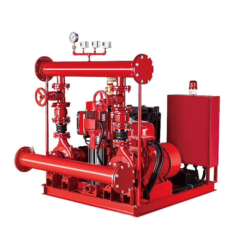 Fire Pump and System
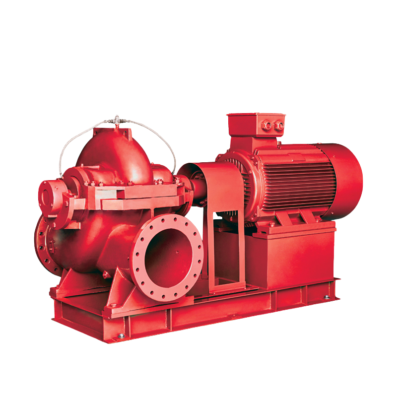 Split Case Pump
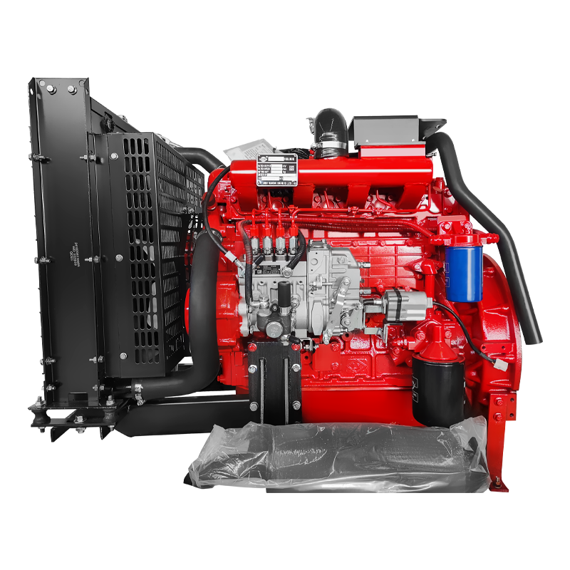 Engine and Pump
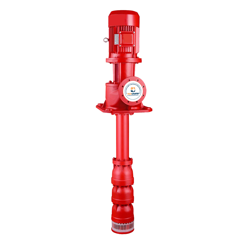 Long Shaft Pump
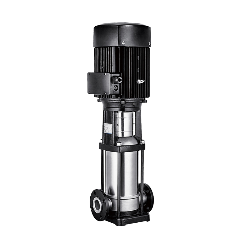 Multistage pump
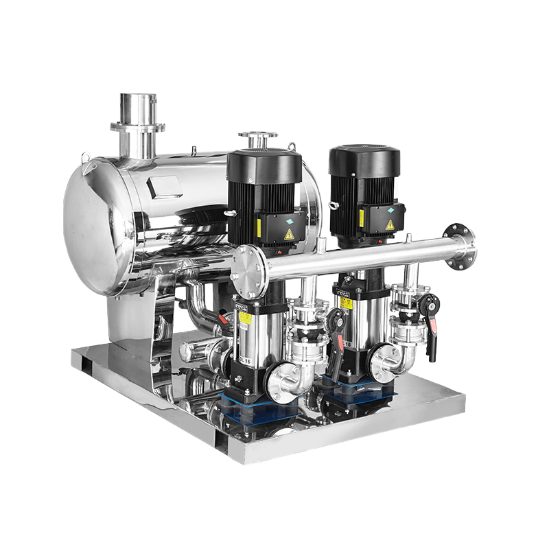 Water Supplier System
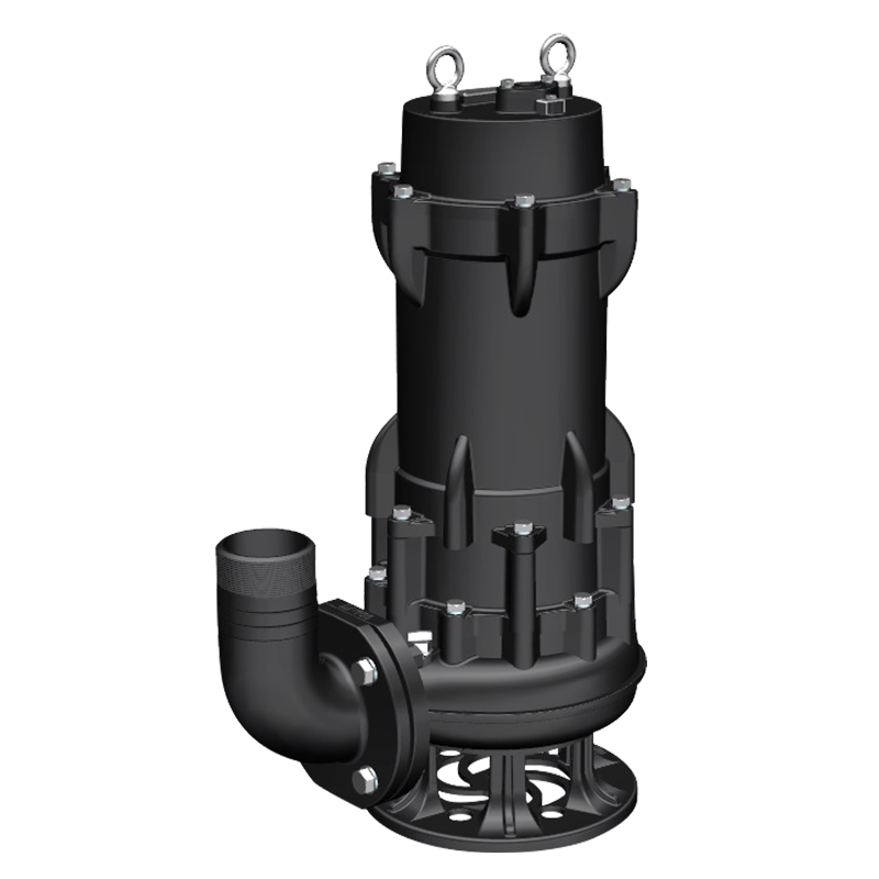 Sewage Pump
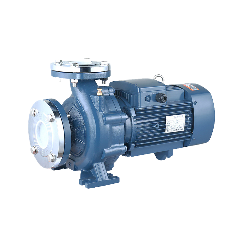 Industrial Pump
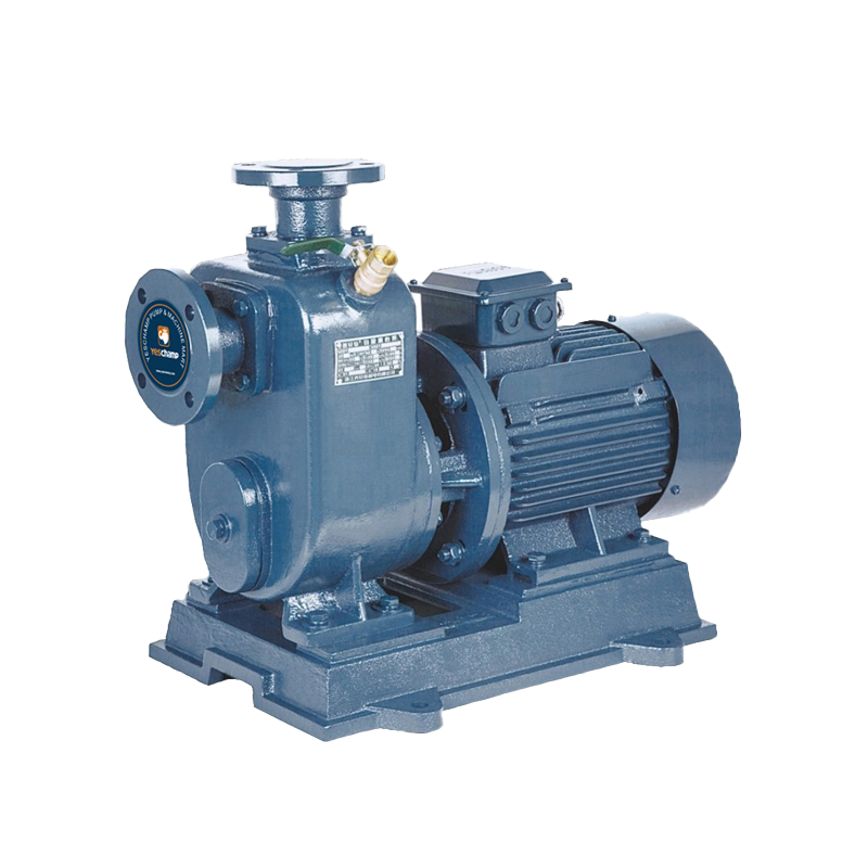 Self-Priming Pump
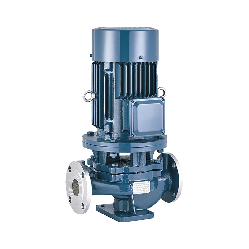 Inline Pump
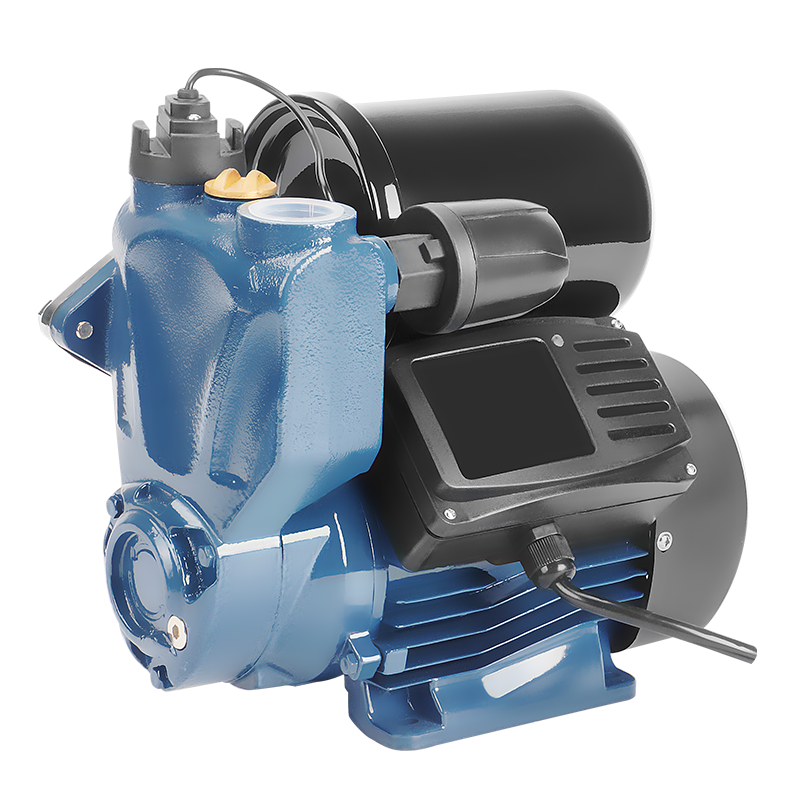 Domestic Pump
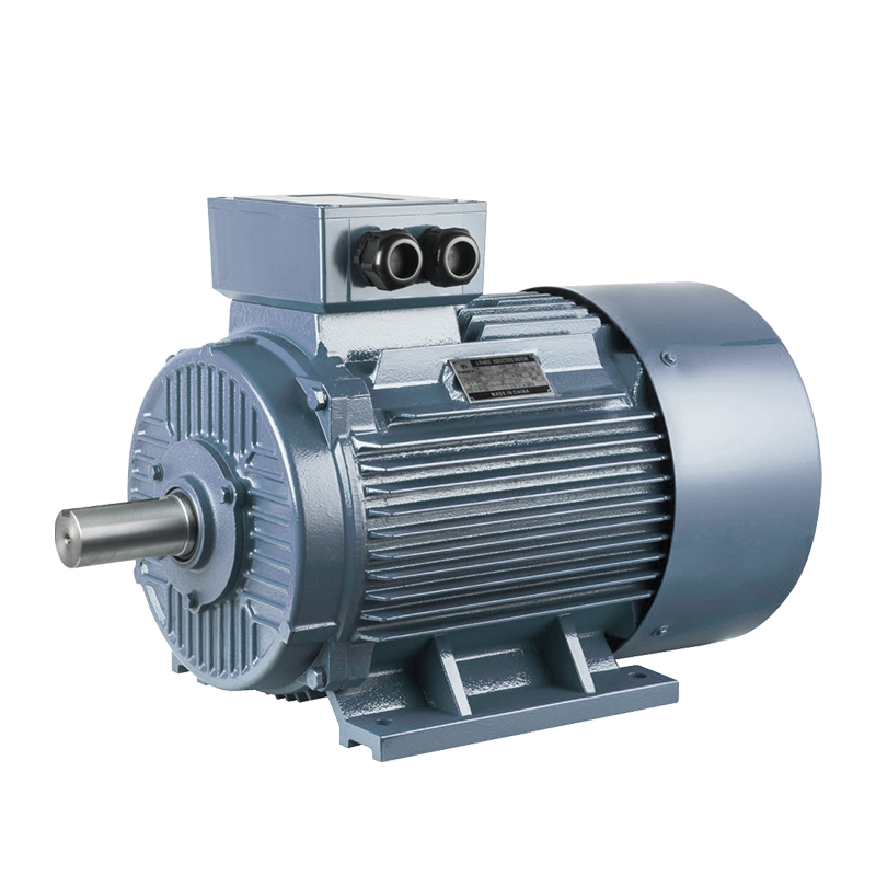 Electric Motor
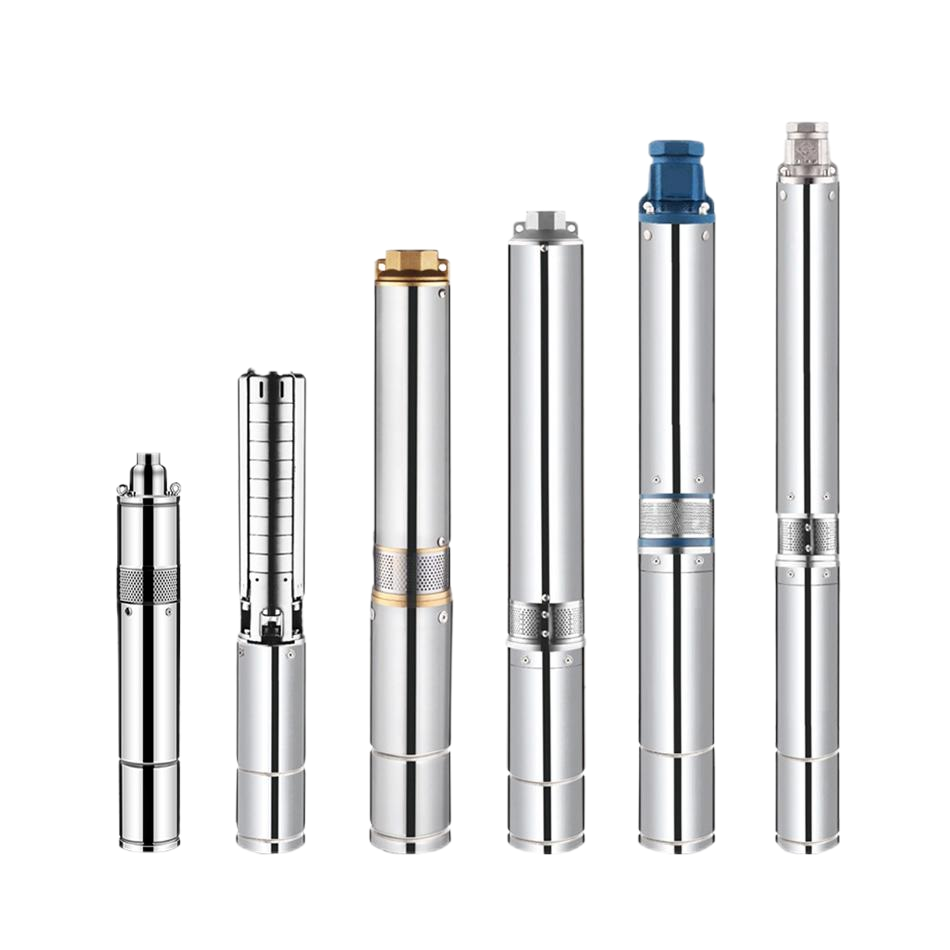 Borehole Pump
Non-Negative Pressure Water Supply System: Design and Selection Guide
Designing a non-negative pressure water supply system requires more than selecting a booster pump with a suitable motor power. The designer must balance building demand, upstream pressure, available inlet flow, pump head, pressure-stabilizing volume, control logic, pipe losses, water quality, local utility requirements, and future operating conditions. The objective is to increase downstream pressure without drawing the upstream network into an unacceptable negative-pressure condition.
A well-designed system can use available municipal pressure, reduce the need for a large conventional storage tank, stabilize water delivery, and lower energy consumption through variable-speed control. A poorly designed system may cause pressure fluctuation, pump cycling, cavitation, upstream drawdown, insufficient flow, or premature equipment failure. This guide explains the complete design and selection process, from collecting project data to choosing pumps, tanks, sensors, controls, pipework, and protective devices.
What Is a Non-Negative Pressure Water Supply System?
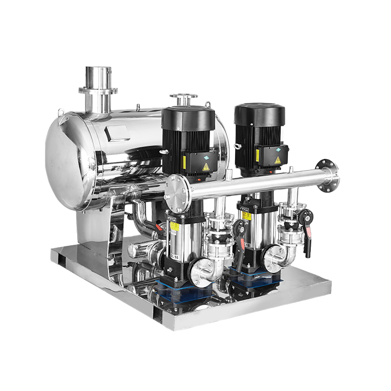
A non-negative pressure water supply system is a controlled direct-connected booster arrangement that raises water pressure while maintaining a safe pressure condition at the inlet. It normally includes booster pumps, a pressure-stabilizing tank or buffer vessel, inlet and outlet pressure sensors, a control cabinet, valves, check valves, bypass equipment, and low-inlet-pressure protection.
Unlike a conventional booster set that draws from a large break tank, this system can make use of the pressure already available in the municipal or upstream pipe. When the upstream pressure is sufficient, the system may pass water through with limited pump assistance. When demand increases or the downstream pressure falls, the booster pumps add the required pressure. The controller continuously adjusts the operating condition according to inlet pressure, outlet pressure, and flow demand.
The phrase “non-negative pressure” does not mean that the system can operate without any hydraulic limitation. It means that the design and control strategy are intended to prevent excessive pressure reduction at the upstream connection. The system must still have a defined minimum inlet pressure, minimum available flow, low-pressure shutdown point, and safe response to abnormal supply conditions.
Design Objectives and Operating Boundaries
The first design objective is to deliver the required outlet pressure and flow at the most demanding operating point. This may be the highest floor in a residential tower, the most distant fixture in a commercial building, or a process user at the end of an industrial pipeline. The calculation must include elevation, pipe friction, valves, fittings, equipment losses, and the minimum residual pressure required at the outlet.
The second objective is to protect the upstream network. The system should not use the booster pumps to draw more water than the upstream pipe can provide. When inlet pressure or flow falls below the permitted value, the controller should reduce pump speed, stop a pump, open an approved bypass, or issue an alarm. The response must be defined before equipment selection rather than added after commissioning.
The third objective is stable and efficient operation across the full demand range. Most water systems do not operate continuously at peak flow. A pump set designed only around peak demand may be oversized during normal use, causing frequent starts, throttling, poor efficiency, and pressure fluctuation. Multiple pumps, variable-frequency drives, and a suitable buffer tank can help match supply to actual demand.
The fourth objective is serviceability. The equipment room should provide space for pump removal, sensor replacement, tank inspection, control-cabinet access, drainage, and safe isolation. Spare parts, control documentation, alarm records, and commissioning data should be available to the operations team from the beginning.
Step 1: Collect the Required Design Data
A reliable selection begins with accurate project data. Collect the building or process layout, number of floors, highest and most distant outlets, pipe routing, fixture schedule, equipment pressure requirements, expected occupancy, operating hours, seasonal demand, and future expansion plans. For industrial applications, include production cycles, cleaning demand, cooling-water demand, and any simultaneous process loads.
Measure or obtain the upstream pressure under several conditions. At minimum, identify maximum, normal, and minimum inlet pressure, along with the corresponding available flow. A static pressure measured at night may be much higher than the pressure available during morning demand. The system should be designed around the credible minimum condition, not an optimistic single measurement.
Record the available pipe size, connection location, material, upstream valve arrangement, meter, filter, and restrictions. Identify whether the water authority permits direct connection and whether it requires a bypass, backflow prevention device, flow limiter, monitoring point, or approval drawing. Utility requirements can affect the entire system architecture.
Water quality data should include temperature, pH, hardness, suspended solids, corrosiveness, and hygiene requirements. Clean domestic water may allow stainless steel wetted components and standard elastomers. Industrial or treated water may require special materials, filtration, or a different pump design. These inputs should be documented before the pump and tank materials are chosen.
Step 2: Calculate Design Flow Rate
The design flow rate should represent realistic simultaneous demand. For residential buildings, consider fixture units, occupancy, usage patterns, and local plumbing calculation methods. For hotels, hospitals, schools, and offices, consider peak periods, building function, and the probability of simultaneous use. For factories, calculate the flow required by actual processes rather than applying a general building allowance.
Use at least three operating points: minimum flow, normal design flow, and peak flow. Minimum flow helps determine whether the system will cycle or operate unstably. Normal flow is the point at which the system will spend most of its operating hours. Peak flow determines the maximum pump capacity and the required number of pumps operating together.
Avoid selecting the pump by simply adding the nominal flow of every outlet. That method may significantly oversize the system. At the same time, do not reduce the peak demand so aggressively that the outlet pressure falls during a realistic high-use event. The design calculation should be recorded so that the selected pump capacity can be reviewed later.
Flow-Rate Selection Table
Step 3: Calculate Total Dynamic Head
Total dynamic head is the pressure that the booster system must add to meet the required outlet condition. It commonly includes the elevation difference between the inlet and the highest outlet, friction loss in straight pipe, local losses from fittings and valves, equipment pressure drop, and the minimum residual pressure required at the user point.
A practical calculation can be expressed as:
Required pump head = static elevation head + pipe and fitting losses + equipment losses + required residual head − available inlet head.
All terms must use consistent units. The available inlet head should be based on the minimum credible pressure at the design flow, not only on static pressure. If the inlet pressure changes substantially, calculate the required booster head at more than one inlet condition. The pump control range must cover the difference without creating excessive discharge pressure when inlet pressure is high.
The designer should also check maximum pressure. At low building demand, a pump may reach a higher pressure than expected, especially if the upstream supply already provides significant pressure. The system must remain within the pressure rating of pipes, valves, fixtures, tanks, seals, and connected equipment. A pressure relief or control strategy may be required where the operating range is wide.
Step 4: Evaluate Inlet Pressure and Non-Negative Protection
Inlet pressure is the defining design condition for a non-negative pressure system. The designer should determine the minimum pressure at the connection point during peak upstream demand, the pressure available at minimum municipal supply, and the lowest pressure that the equipment can safely accept. These values should be verified through measurement, utility data, or a hydraulic study.
The inlet protection sequence should be clearly defined. For example, when inlet pressure falls below the warning value, the controller may reduce pump speed or limit the maximum number of operating pumps. At a lower shutdown value, the system may stop the booster pumps and generate an alarm. When pressure recovers, the system may restart after a delay and confirmation that the condition is stable.
The minimum inlet flow must also be considered. Pressure alone does not prove that enough water is available. A large pressure reading can still be followed by a rapid pressure collapse when the booster begins drawing water. Test the inlet under representative flow conditions and include the upstream pipe, meter, filters, valves, and connection losses in the analysis.
A bypass may be used to maintain limited supply or provide an alternative flow path, but it should not be treated as a substitute for a complete hydraulic design. Check valves, backflow prevention, pressure regulators, vacuum protection, and flow-control devices must be selected and arranged so that they do not create unintended restrictions or reverse flow.
Step 5: Select the Pump Arrangement
The pump arrangement should match the flow range, pressure requirement, redundancy target, and maintenance strategy. A single pump may be acceptable for a small installation with limited duty variation and low consequence of downtime. A parallel multi-pump set is usually more flexible because it can operate one pump at low demand and add pumps as demand increases.
Vertical multistage pumps are often used when high pressure is required in a compact footprint. Horizontal centrifugal pumps may be appropriate when floor space, suction conditions, and maintenance access favor a horizontal arrangement. End-suction pumps, in-line pumps, or packaged variable-speed booster sets can also be considered. The selection should be based on the actual performance curve, not the pump category alone.
A typical multi-pump design may use two duty pumps plus one standby pump, or several smaller pumps that stage according to demand. Redundancy should be stated clearly: does one remaining pump need to cover the full normal demand, the peak demand, or only a defined emergency flow? The answer affects equipment cost, pipe size, control logic, and electrical capacity.
The pumps should operate near their best efficiency point during normal demand. If the normal flow is much lower than the combined capacity, use staging, variable-speed drives, a smaller pressure-maintenance pump, or another control method to avoid prolonged throttling and rapid cycling. Confirm the minimum continuous flow and minimum speed for each pump.
Pump Arrangement Comparison
Step 6: Select the Pressure-Stabilizing Tank
The pressure-stabilizing tank provides a buffer between pump operation and rapid changes in demand. It can reduce short cycling, absorb small pressure fluctuations, and help the controller maintain a stable pressure during transitions. Tank selection must consider operating pressure, connection size, material, water-contact requirements, internal diaphragm or air space, and the expected number of pump starts.
Do not size the tank only by copying the volume of a conventional storage tank. A buffer tank in a non-negative pressure system has a different function from a reserve water tank. The required volume depends on pump minimum capacity, control dead band, expected low-flow duration, pressure range, and acceptable start frequency.
The tank should be installed where it can be isolated, drained, inspected, and replaced. The connection should not create excessive pressure loss or trap air in an undesirable location. If a diaphragm or air precharge is used, the precharge value should be set and checked according to the manufacturer’s instructions and operating pressure.
An incorrectly sized or incorrectly charged tank may cause frequent starts, pressure oscillation, or insufficient buffering. During commissioning, record the tank condition and verify actual cycling behavior at low and intermittent demand.
Step 7: Design the Control System
The control system is responsible for maintaining outlet pressure while protecting the inlet network and the pumps. It should receive inlet pressure, outlet pressure, and, where necessary, flow signals. The controller then determines pump speed, pump staging, start and stop timing, alternation, standby changeover, and alarm status.
A variable-frequency drive can adjust motor speed to match changing demand. This may reduce energy use and pressure surges, but it does not remove the need for correct pump selection. The drive must operate within the motor’s permitted speed range and the pump’s minimum flow and cooling requirements. Very low speed may cause inadequate motor cooling, unstable hydraulics, or insufficient seal lubrication.
Pump alternation helps distribute operating hours among parallel units. Automatic standby changeover can start another pump when the duty pump fails, trips, or exceeds a defined operating time. The changeover sequence should avoid simultaneous uncontrolled starts and should report the cause of the changeover to the operator.
Minimum protection functions normally include low inlet pressure, dry run, motor overload, overtemperature, sensor failure, phase loss, power failure, communication failure, and emergency stop. Alarm priorities should distinguish between a warning that permits continued operation and a fault that requires shutdown.
Design of Inlet and Outlet Pipework
The inlet pipe should be sized to limit friction loss and maintain stable pressure at the pump suction. It should be as direct as possible, with gradual changes in direction and no unnecessary restrictions. Pipework should be independently supported so that the pump casing and flexible connectors do not carry external loads.
Install the inlet pressure sensor in a representative location, away from turbulence caused by elbows, valves, or pump suction. If a strainer or filter is used, provide enough filtration area and a clear maintenance procedure. A blocked filter can create false low-pressure alarms and may push the system into an unnecessary shutdown.
The outlet pipe should be sized for the maximum design flow while considering velocity, noise, friction, and future expansion. Install check valves to prevent reverse flow and isolation valves to support maintenance. Pressure gauges should be installed at locations that allow commissioning technicians to compare sensor readings with mechanical instruments.
Bypass and pressure-relief arrangements must be designed as part of the system, not added informally in the field. The bypass should not allow uncontrolled reverse flow or create a path that defeats inlet-pressure protection. Any backflow prevention device, flow limiter, or pressure regulator should be included in the hydraulic loss calculation.
Materials, Power, and Equipment-Room Selection
For clean domestic water, stainless steel pump components may offer good corrosion resistance and a smooth wetted surface. Carbon steel, cast iron, coated components, or special alloys may also be suitable depending on water chemistry, cost, and pressure rating. Confirm the material of the pump casing, impellers, shaft, seals, tank, valves, and pipe connections rather than assuming that the whole package uses one material.
The electrical system must provide adequate voltage, phase, frequency, short-circuit protection, motor starting capacity, cable size, grounding, and control power. Variable-frequency drives require ventilation and protection from heat, moisture, dust, and electromagnetic interference. The available electrical capacity should be checked against the maximum number of pumps operating simultaneously.
The equipment room should include drainage, lighting, ventilation, noise control, safe access, lifting or removal space, and protection from flooding. The control cabinet should be accessible without blocking pipe valves or pump maintenance areas. A clear equipment layout reduces service time and lowers the risk of accidental isolation or incorrect operation.
Selection Checklist and Supplier Documents
Before final selection, prepare a technical schedule that lists design flow, normal flow, peak flow, required head, minimum and maximum inlet pressure, water temperature, water quality, power supply, pump arrangement, tank requirements, control functions, and installation constraints. This schedule should be sent to each supplier so that proposals can be compared on the same basis.
Request pump performance curves showing the normal and peak operating points. Ask for motor power, efficiency, speed range, minimum flow, noise data, NPSH-related information, materials, mechanical-seal details, and allowable operating limits. For the control panel, request a sequence description, alarm list, sensor ranges, variable-frequency drive details, communication options, and factory test procedure.
The supplier should also provide a general arrangement drawing, foundation loads, connection sizes, electrical data, tank details, valve list, spare-parts recommendations, installation instructions, commissioning procedure, maintenance schedule, and warranty conditions. If the system is subject to utility or project approval, request certificates and compliance documents at the quotation stage.
Required Selection Data
Commissioning and Acceptance Testing
Commissioning should start with a review of drawings, equipment tags, pump curves, wiring diagrams, control logic, and sensor locations. Confirm that the delivered pump set, tank, valves, sensors, control cabinet, and protective devices match the approved specification. Check that the pipelines have been flushed and that strainers are clean.
Fill and vent the pump set according to the manufacturer’s procedure. Verify inlet pressure, outlet pressure, tank condition, valve positions, motor rotation, sensor signal ranges, and controller status. Start the system at low demand and observe pressure stability, pump speed, current, vibration, leakage, and noise.
Test normal, minimum, and peak simulated demand. Confirm that pumps stage correctly, variable-speed control responds smoothly, the system uses available inlet pressure, and the outlet pressure remains within the target range. Test a low inlet-pressure condition and verify that the system limits or stops operation according to the approved sequence.
Test overload, dry-run, sensor failure, communication failure, power loss, emergency stop, and standby changeover functions. Each alarm should produce a clear indication and a safe system response. Do not leave temporary bypasses or disabled protection functions in place after testing.
The acceptance report should record inlet pressure, outlet pressure, flow, pump speed, motor current, pump combination, tank settings, alarm results, sensor calibration, and final controller parameters. Operators should receive training and copies of the final drawings, manuals, alarm list, and maintenance schedule.
Common Design Errors and Troubleshooting
A common design error is selecting the pump using only the peak head and peak flow while ignoring normal and minimum demand. This can result in oversized pumps, frequent cycling, throttling, unstable pressure, and unnecessary energy use. Review the full demand curve and consider staged or variable-speed operation.
Another error is using static inlet pressure as the design pressure. Inlet pressure may fall sharply when the upstream network is busy or when the booster begins drawing water. Use minimum pressure under representative flow conditions and include the upstream pipe, meter, filter, and valve losses.
If the outlet pressure is too low, check pump rotation, inlet pressure, inlet filter, valve position, sensor accuracy, actual flow, pipe losses, and the pump curve. If pressure fluctuates, inspect control response, sensor location, tank precharge, pump staging, check valves, and communication signals.
If the inlet pressure falls into an unacceptable range, do not simply increase the pump speed or pressure setpoint. Check the available upstream flow, connection size, filter blockage, upstream valve, municipal pressure, and pump capacity. The correct response may be capacity limitation, a larger upstream connection, a storage tank, or a revised system design.
Frequent pump starts may indicate leakage, a failed check valve, insufficient buffer volume, incorrect pressure dead band, sensor drift, or a pump that is too large for the normal demand. Severe noise or vibration may indicate cavitation, air ingress, dry running, pipe strain, misalignment, or worn bearings. Troubleshoot the hydraulic and control system together rather than replacing parts without checking the operating data.
Conclusion: How to Design and Select the Right System
A non-negative pressure water supply system should be designed as an integrated hydraulic, mechanical, electrical, and control package. The key steps are to define realistic flow rates, calculate total dynamic head, measure minimum inlet pressure and available flow, protect the upstream network, select the correct pump arrangement, size the pressure-stabilizing tank, design stable controls, and provide suitable pipework, power, maintenance access, and documentation.
The best system is not necessarily the one with the largest pump or the highest pressure setpoint. It is the system that maintains the required outlet pressure across the real demand range while using available inlet pressure safely and efficiently. Before purchase, request complete performance curves, pressure and flow data, tank specifications, control logic, sensor ranges, protection functions, drawings, commissioning procedures, spare-parts information, and warranty terms. A careful design and selection process helps prevent low pressure, upstream drawdown, cavitation, excessive cycling, energy waste, and premature equipment failure.
Non-Negative Pressure Water Supply System FAQ
What is the main design objective of a non-negative pressure water supply system?
The main objective is to provide the required downstream flow and pressure while preventing excessive pressure reduction at the upstream connection. The system uses booster pumps, sensors, a pressure-stabilizing tank, and protective controls to respond to changing demand. The design must define minimum inlet pressure, available flow, low-pressure protection, and a safe response to abnormal supply conditions.
How do I calculate the required booster pump head?
Calculate the static elevation head, pipe and fitting losses, equipment pressure losses, and the minimum residual pressure required at the most demanding outlet. Then subtract the available inlet pressure head at the design flow. The result is the approximate booster head required at that operating point. Use consistent units and verify the result against the pump performance curve.
How should the minimum inlet pressure be determined?
Measure or obtain the pressure under the most demanding credible upstream condition, not only during low-demand periods. Consider the municipal pipe, meter, filters, valves, connection losses, and the flow drawn by the booster. The design should use the minimum available pressure and include a defined warning and shutdown limit.
How do I select the number of booster pumps?
Select the number of pumps according to normal and peak demand, desired redundancy, minimum stable flow, maintenance requirements, and available electrical capacity. Parallel pumps provide flexible flow staging, while a duty-and-standby arrangement can improve availability. Confirm whether one remaining pump must cover normal, peak, or emergency demand.
What is the function of the pressure-stabilizing tank?
The tank provides a limited hydraulic buffer that reduces short cycling and absorbs small pressure changes. Its volume depends on pump minimum capacity, pressure dead band, low-flow duration, acceptable start frequency, and system control logic. It should not be sized as if it were a conventional reserve storage tank without reviewing the system design.
Can a non-negative pressure system work with a variable-frequency drive?
Yes. Variable-frequency drives are commonly used to adjust pump speed to changing demand and maintain a stable outlet pressure. The drive must be compatible with the motor and pump, and its minimum speed, minimum flow, cooling, acceleration, and protection settings must be defined. Variable-speed control cannot compensate for an inadequate water source or an incorrectly sized pump.
 5th Floor, Comprehensive Building No. 5, Dongqiao, Dong'an Village, Daxi Town,Wenling City,Zhejiang,China
 +86 576 86090666

 +86 18667600006
 +86 18667600006
 24 Hours Online
