 3D ROOM
 (0)
(0) English
 عربى
عربى
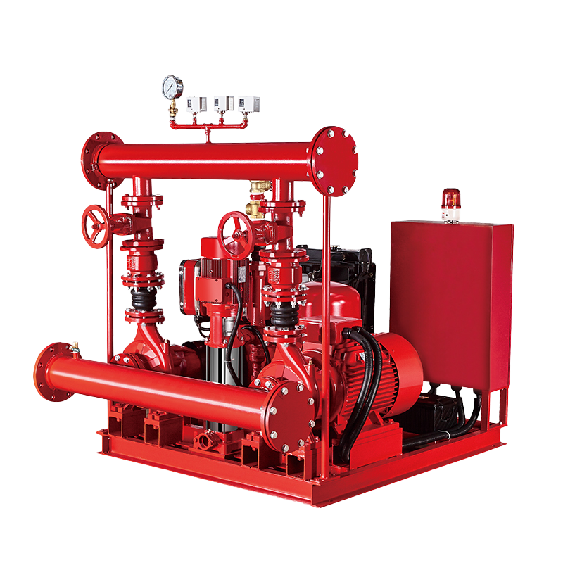 Fire Pump and System
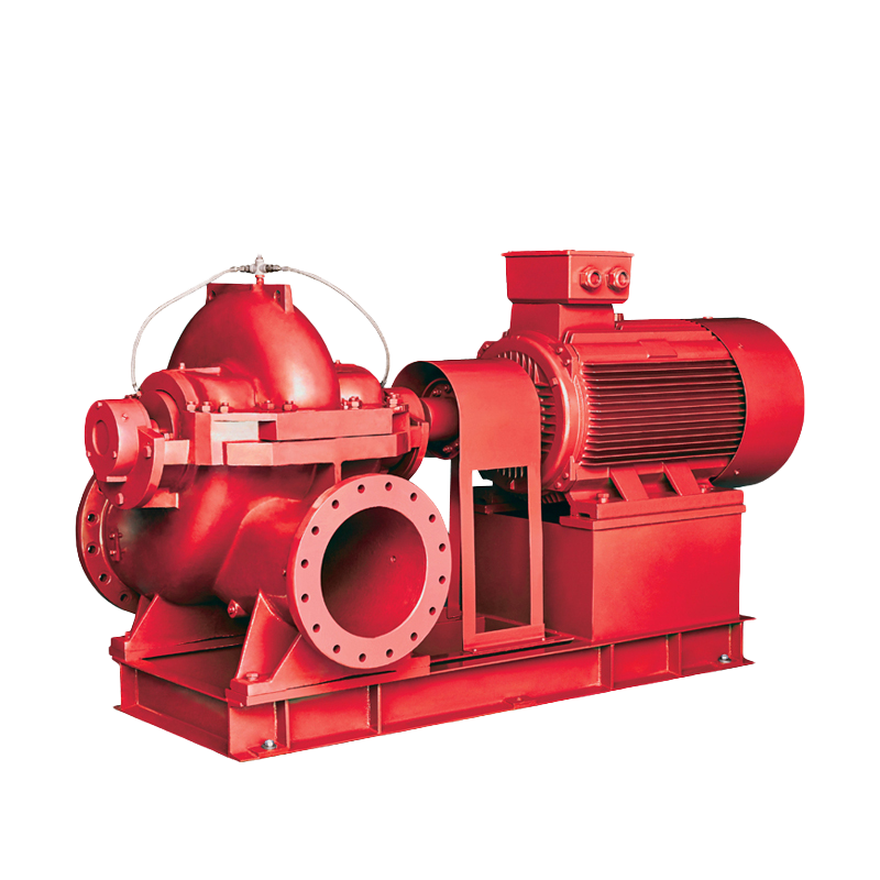 Split Case Pump
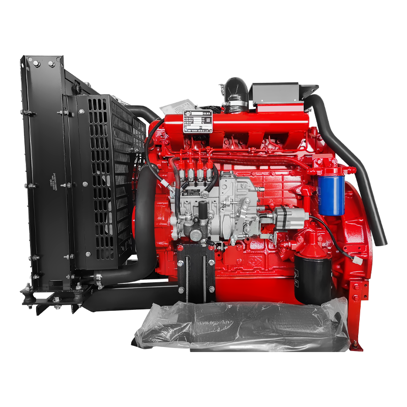 Engine and Pump
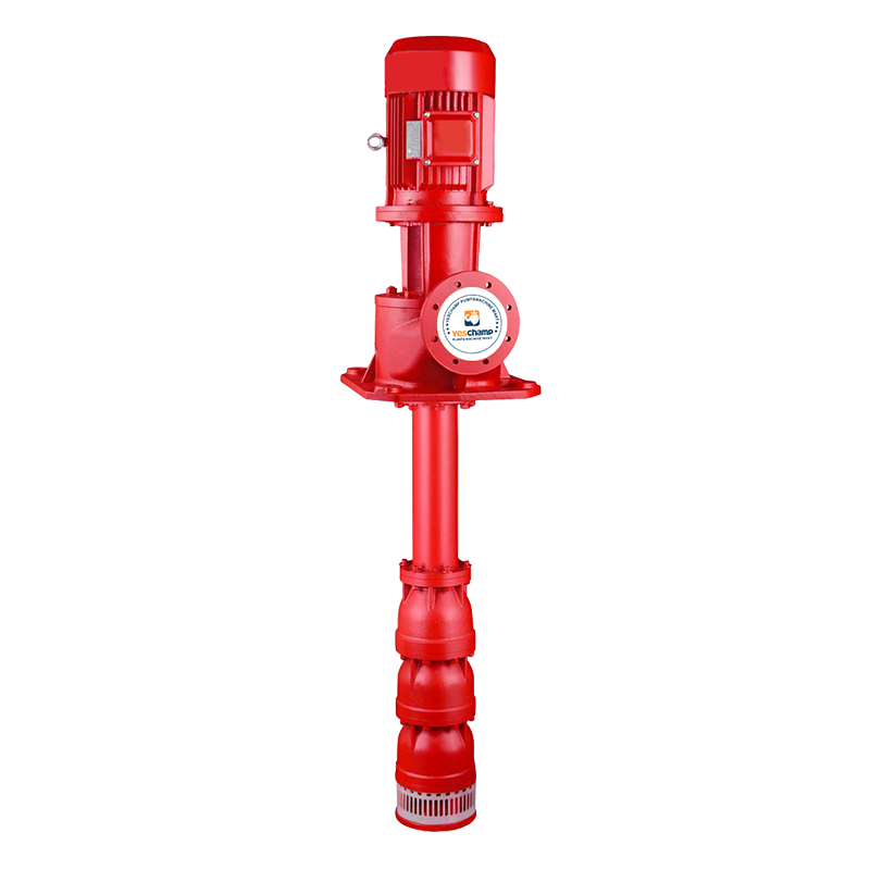 Long Shaft Pump
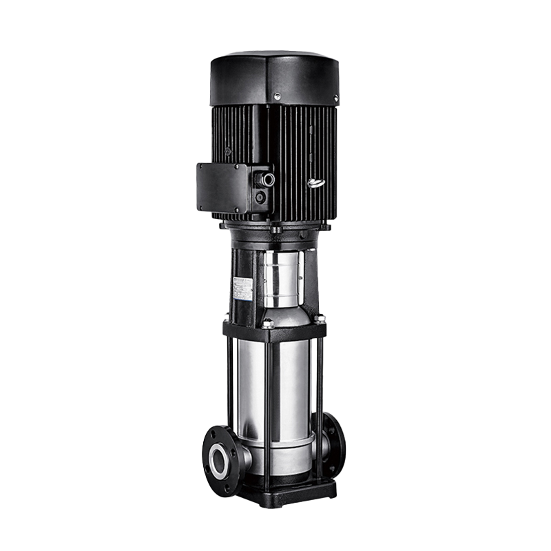 Multistage pump
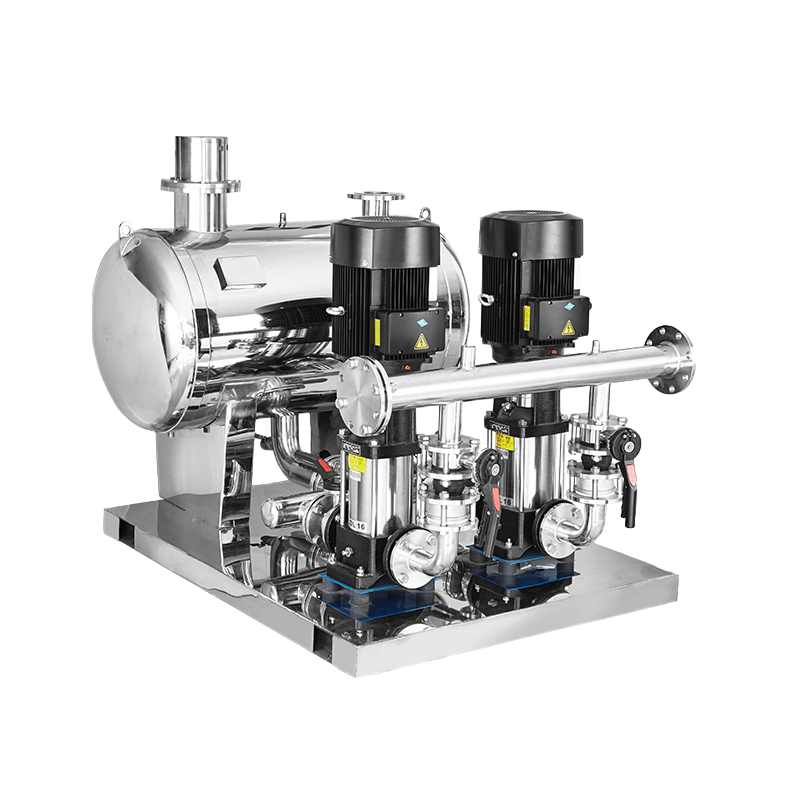 Water Supplier System
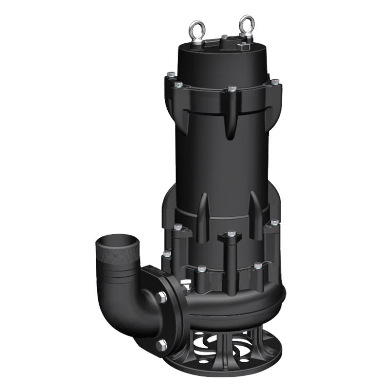 Sewage Pump
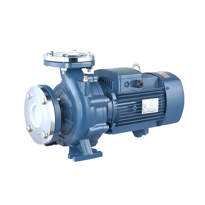 Industrial Pump
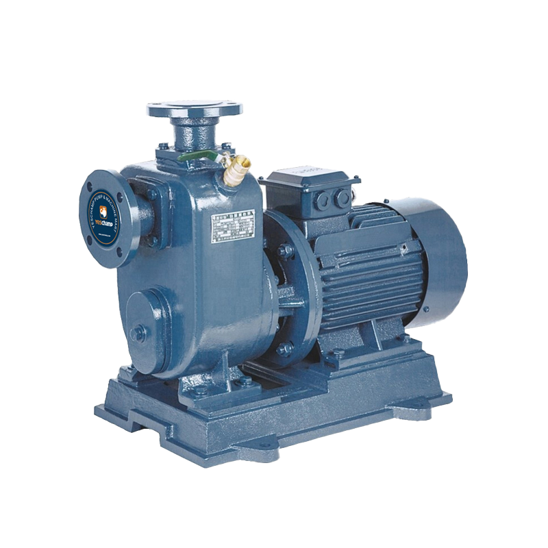 Self-Priming Pump
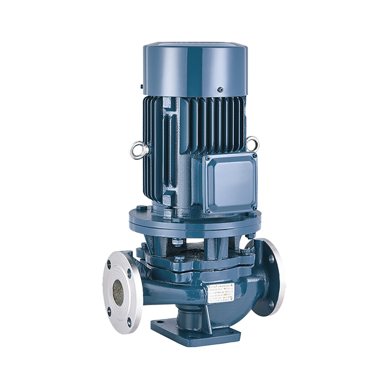 Inline Pump
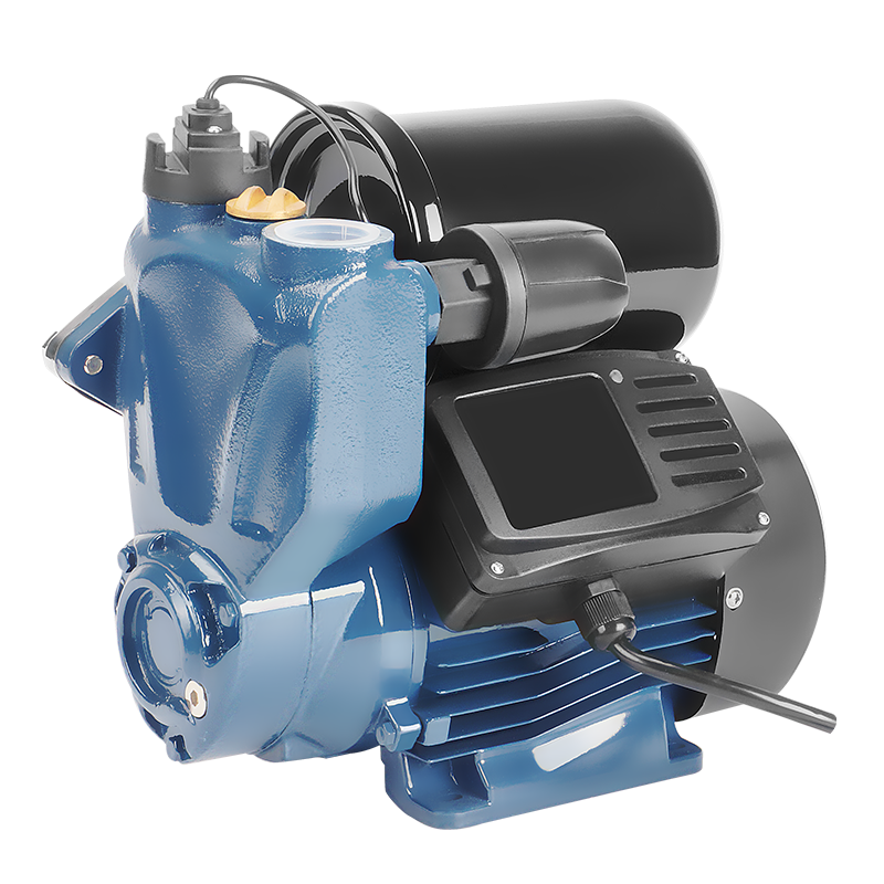 Domestic Pump
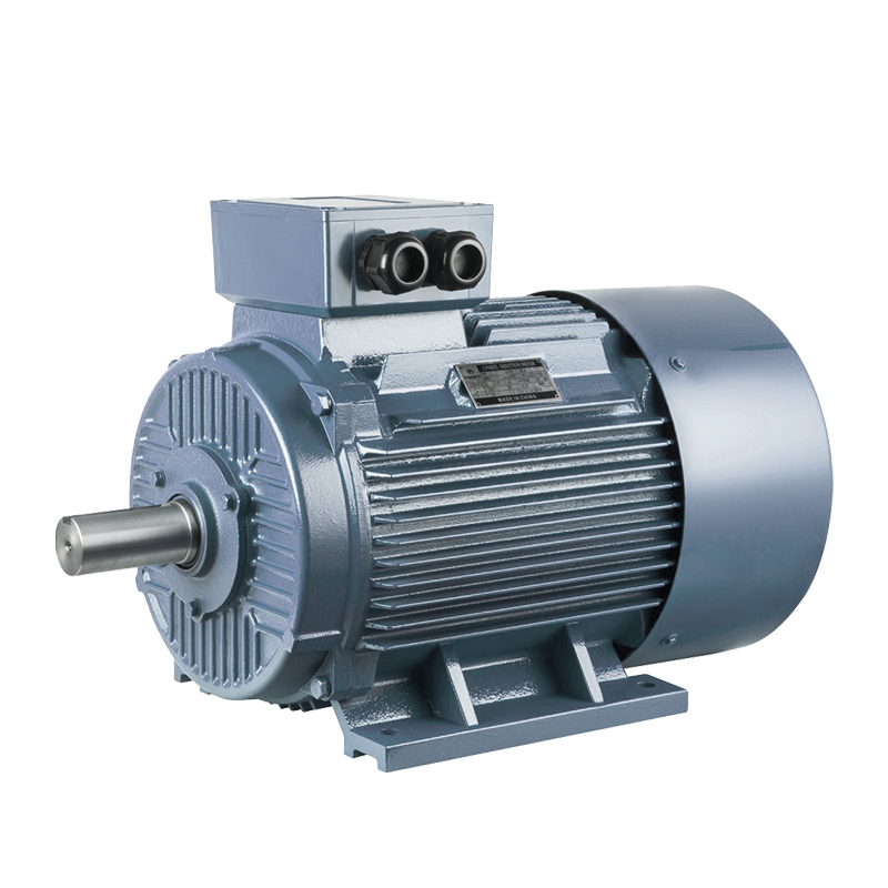 Electric Motor
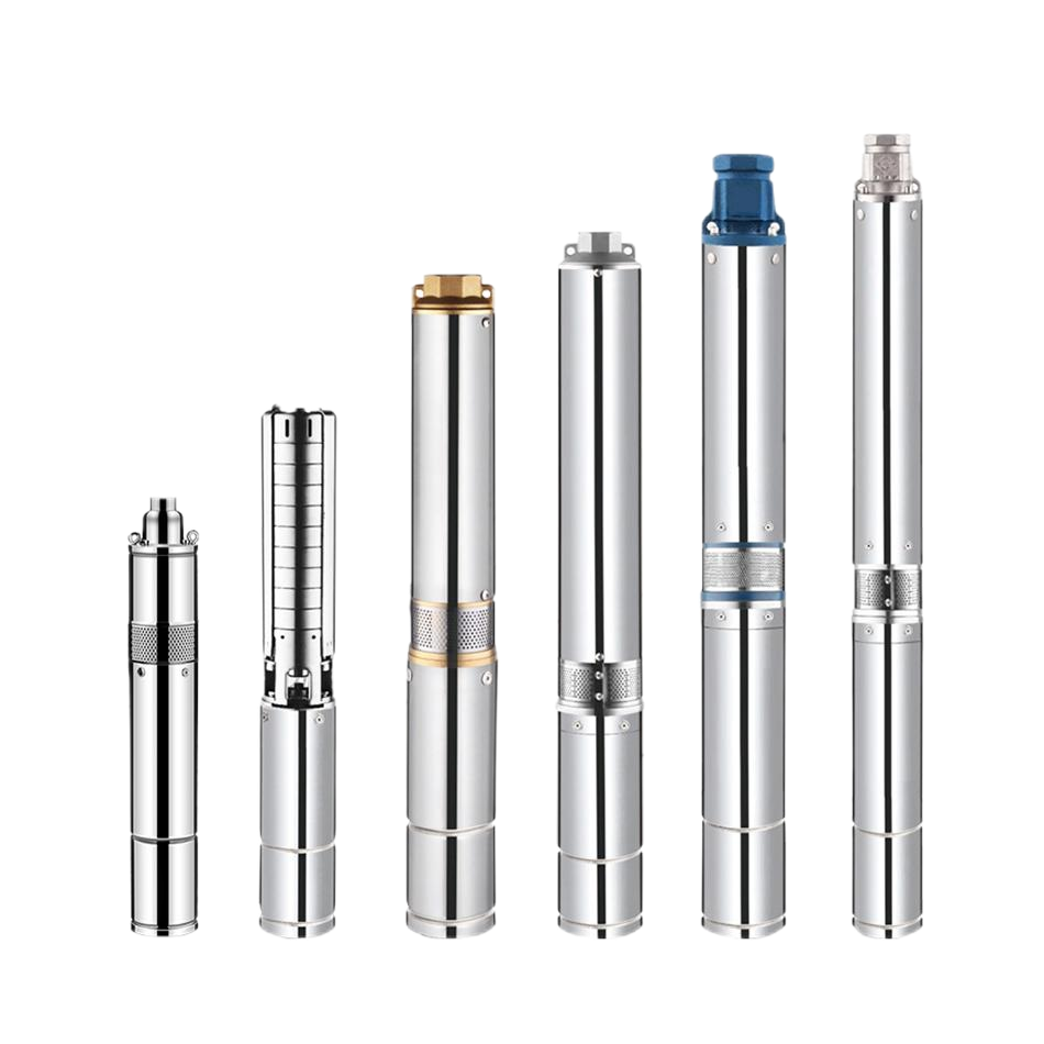 Borehole Pump
EDJ Fire Pump System: Components, Specifications, and How to Choose One
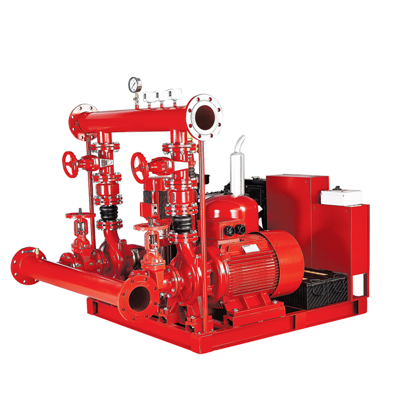
An EDJ fire pump system is a packaged fire-fighting water supply — pump end, driver, controller, jockey pump and accessories — engineered to deliver a rated flow and pressure to a sprinkler network, standpipe, hydrant system or foam system the moment a fire is detected. YESCHAMP builds the EDJ series for projects that want a factory-assembled, test-verified package instead of loose components assembled on site, with rated capacities up to 2,500 US GPM (roughly 568 m³/h, or 158 L/s).
This guide explains what the system contains, how to read its specifications, how to size it for a real project, and what installation, acceptance testing and maintenance actually require.
What Is an EDJ Fire Pump System?
A fire pump system is the engine room of a building's water-based fire protection. Sprinklers, hose reels and hydrants need a minimum residual pressure at the most remote outlet; the public main or an on-site storage tank often cannot provide that pressure on its own. The fire pump closes that gap by boosting water from the supply to the demand point.
An EDJ system therefore differs from an ordinary booster pump in three practical ways. First, it is engineered around a rated point — a specific flow and head combination — rather than around average daily demand. Second, it is built to keep running under conditions a domestic pump would never see: prolonged operation, high suction temperatures, and electrical overload. Third, it is a package: pump, driver, controller, jockey pump, pressure relief valve, sensing lines and valves are matched by one manufacturer, which removes the most common site failure — a pump, motor and controller that were never designed to work together.
Typical installations include high-rise residential and commercial towers, shopping malls, hotels, hospitals, warehouses and logistics parks, factories, data centres, and fuel or chemical storage sites where water demand and pressure both run high. In every case the system is a life-safety asset: it is expected to work after years of inactivity, on the first demand, without an operator present.
Inside an EDJ Fire Pump System: Components and Working Principle
The pump end
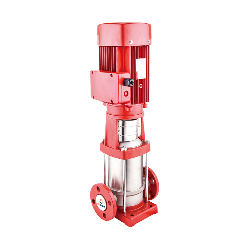
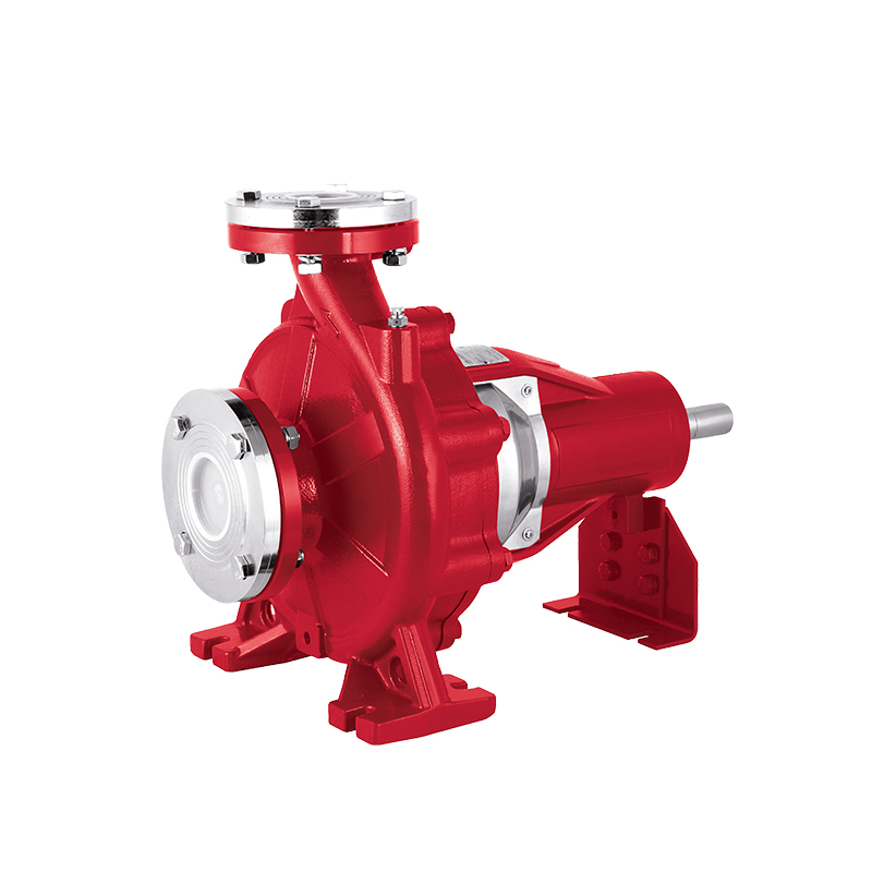
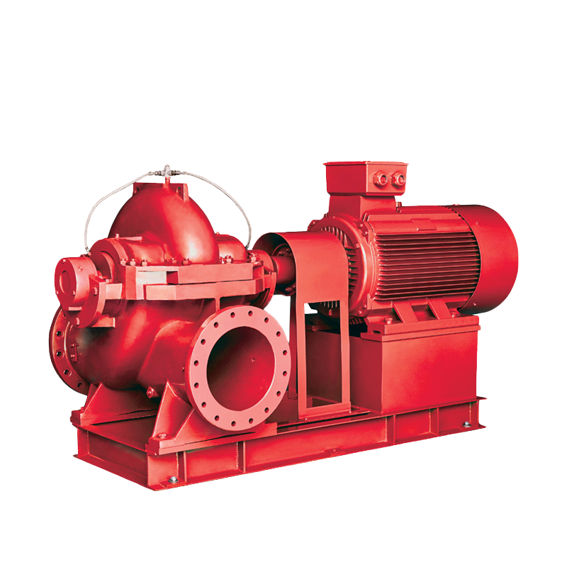
The pump end converts driver rotation into flow and pressure. End-suction, split-case and vertical-turbine constructions are used across the fire pump market, and each suits different suction conditions, footprints and flow ranges — end-suction where space and suction lift are modest, split-case where high flow and easy maintenance access matter, vertical-turbine where the water source is a tank or an open body of water below floor level. The correct choice follows the hydraulic calculation, not the other way round.
The driver
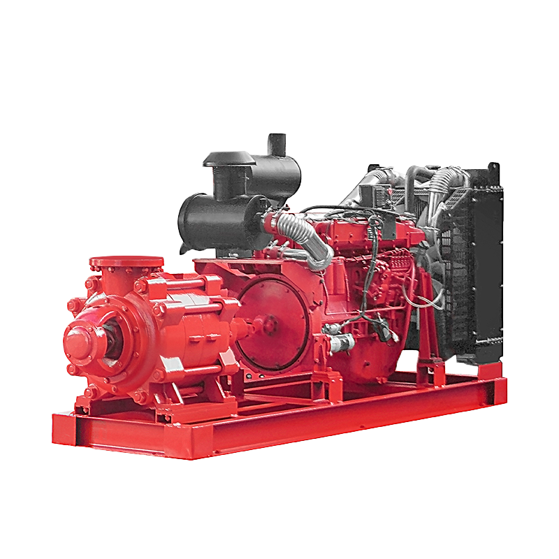
The driver is either an electric motor or a diesel engine, and it determines the power supply, the room layout, the fuel or cable routing, and the maintenance routine. Electric drive is quieter, cleaner and cheaper to operate where a reliable power supply exists; diesel drive is preferred where the supply is unreliable or where the authority having jurisdiction requires an independent driver.
The controller
The controller starts and stops the pump automatically by monitoring system pressure, and it is the component that most often decides whether a system behaves well in service. Fire pump controllers are deliberately designed not to shut the pump down on overload: an interrupted fire fight is more dangerous than a damaged pump, so the controller holds the pump running and lets the protection device react only to a genuine short circuit.
Jockey pump, valves and accessories
A small jockey (pressure-maintenance) pump holds system pressure between the controller's cut-out and cut-in points so that minor leakage does not start the main pump. Around it sit the discharge check and gate valves, the pressure relief valve that protects the system when pump churn pressure exceeds component ratings, pressure-sensing lines, a flow meter where permitted, and a test header that lets the acceptance test be run without wetting the building.
How it works: when a sprinkler head opens, pressure in the system falls. The jockey pump starts first to absorb small drops. If pressure keeps falling — the signature of a real fire — the controller starts the main pump at its set cut-in pressure and holds it running. Pressure relief and sensing lines keep the resulting pressure within the design envelope.
Key Specifications: Flow, Head, and Pressure
Three numbers define any fire pump system, and they are read together, never in isolation.
Rated flow is the flow at which the pump is expected to perform — for example 500, 1,000 or 2,500 US GPM. Rated head is the pressure the pump adds at that flow. Rated pressure is the resulting system pressure at the discharge. A single number is meaningless on its own: a unit quoted at "2,500 GPM" without a corresponding head figure cannot be compared with any other unit.
The 150 per cent point
Standards such as NFPA 20 require a fire pump to deliver at least 65 per cent of its rated head at 150 per cent of rated flow. This is the single most useful test of a curve's shape: it proves the pump keeps supplying water when more sprinkler heads open than the hydraulic calculation assumed. A pump that passes through its rated point but collapses at 150 per cent flow is not suitable, whatever its nameplate says.
Churn pressure
Shut-off, or churn, head is the pressure produced at zero flow, and NFPA 20 limits it to 140 per cent of rated head. Churn pressure also drives two system decisions: whether a pressure relief valve is required, and how the jockey pump cut-in and cut-out points are set. Projects with low-pressure-rated pipe, fittings or sprinkler heads need the churn figure checked before the order is placed, not after.
The EDJ series covers rated capacities up to 2,500 US GPM, with the pump end, driver rating and suction arrangement matched to the project's hydraulic demand and available water source. Capacity, head and driver size are confirmed against the project data sheet and the hydraulic calculation before manufacture.
How to Select the Right EDJ Fire Pump System
Selection is a sequence, and skipping a step moves the risk downstream to the day of the acceptance test.
- Establish the required flow. Start from the hydraulic calculation: the most demanding area of sprinkler operation, plus hose stream allowance where the occupancy requires it. That sum — not a rule of thumb — sets the rated flow.
- Establish the required pressure. The calculation gives you the pressure needed at the most remote outlet. Add elevation and friction losses back to the pump discharge to get the pump's duty point.
- Check the water supply. Confirm what the public main can deliver at the required flow, or size the suction tank. Insufficient suction is the most common cause of a pump failing its own acceptance test.
- Choose the driver. Electric where the power supply is reliable and a standby source is available; diesel where it is not, or where the local code or insurer demands an independent driver.
- Match the controller. The controller must be rated for the pump's motor or engine starting current, configured for the correct start pressure, and — where required — supplied with the alarm and signalling contacts the building's fire alarm system expects.
- Confirm the physical envelope. Plant room dimensions, access for maintenance, weight, fuel storage or cable routes, ventilation, and noise limits all constrain the final configuration. A hydraulically perfect set that cannot be carried into the room is a project delay.
- Document the approvals and the test. Agree in writing which standard governs, which third-party approvals are required for the project, and where the factory test and the site acceptance test will be witnessed.
Each of these steps produces a number or a constraint. When the seven are complete, the EDJ configuration — pump end, rated flow and head, driver, controller and accessories — is defined rather than guessed.
Electric vs Diesel Drive: Which Configuration Fits Your Project
For most projects the driver choice is the biggest single decision, because it changes the room, the maintenance routine and the project cost profile more than any other component.
Two practical points are worth stating plainly. Diesel sets need a fuel supply sized for the required run time — commonly at least one hour at full load per NFPA 20, with many specifications and insurers asking for more — and they rely on battery sets for starting, which is why dual battery arrangements and a disciplined weekly test are part of the package rather than optional extras. Electric sets avoid fuel logistics but inherit the reliability of the grid: a supply that drops during a fire takes the pump with it, unless a standby source is provided.
Where both are acceptable, the honest answer is usually determined by the authority having jurisdiction and the insurer, not by the equipment. Confirm that answer first — it removes a redesign later. See our diesel fire pump sets and fire pump controllers pages for the sub-assembly options.
Installation, Commissioning, and Acceptance Testing
Most failures that appear in the first year are installation failures, not manufacturing failures. The items below are the ones that decide whether the system passes its test on the first attempt.
- Suction conditions. The suction pipe must be free of air pockets, correctly sized, and supported so that the pump is not loaded by pipe weight. A pump that is starved at start will pass no test.
- Sensing lines. These must be connected and located so that the controller sees true system pressure — not a pressure distorted by a closed valve or a dead leg.
- Adequate venting and drainage. The test header, relief valve discharge and room drainage must be able to handle full-flow testing without flooding the plant room.
- Anchoring and alignment. Baseplate grouting, shaft alignment and coupling checks protect the bearings and seals that carry the system through its life.
- Controller settings. Start pressure, jockey cut-in and cut-out, and any time delays must be set and then recorded, so that a later adjustment is a deliberate decision rather than a mystery.
- Acceptance test. The witnessed test typically runs the pump at churn, at 100 per cent and at 150 per cent of rated flow, with readings recorded against the certified curve. Any deviation between the tested curve and the certified curve is a commissioning issue to resolve before handover, not after.
Commissioning also produces the paperwork that the owner will be asked for years later: the certified pump curve, the test record, as-built drawings, controller settings and the maintenance manual. Handover is the right moment to collect these, because assembling them afterwards is far harder.
Testing and Maintenance Schedule
A fire pump system spends its life waiting, so its reliability comes entirely from a disciplined test routine. The schedule below reflects the structure of NFPA 25 practice; the exact interval for a given site follows the edition, the local amendments and the authority having jurisdiction.
Two habits matter more than the table itself. First, record every test: a result without a baseline cannot show a trend, and a slow loss of pressure or flow is exactly the kind of fault that shows up only in records. Second, keep the pump room free of stored materials — a fire pump set that cannot be reached for testing is not a maintained system, however good its paperwork looks.
Common Selection Mistakes to Avoid
- Buying on flow alone. A rated flow without a rated head says nothing about whether the pump suits the project; always compare the full curve.
- Ignoring churn pressure. Systems with pressure-rated components below the pump's churn pressure need a relief valve and a pressure review — a detail that only surfaces during testing if it is missed at specification.
- Undersizing the suction. The pump can only deliver what the supply provides. Tank sizing and suction pipe design belong to the same calculation as the pump selection.
- Mixing unmatched components. A pump, driver and controller from three different sources often means three different assumptions about start pressure, current and rotation.
- Leaving the driver decision late. Electric versus diesel changes the plant room, the fuel or cable infrastructure and the maintenance plan; deciding after the room is built is expensive.
- Skipping the factory test record. The certified curve is what the annual flow test is compared against. Without it, every future test result is an opinion.
Frequently Asked Questions About EDJ Fire Pump Systems
What is an EDJ fire pump system used for?
It supplies boosted water at a defined flow and pressure to a building's fire protection system — sprinklers, standpipes, hydrants or foam — when the incoming supply cannot deliver the required pressure at the most remote outlet. It is a life-safety package, not a general-purpose service pump, and every choice made around it follows from the hydraulic calculation of the protected occupancy.
Can an EDJ fire pump system deliver 2,500 GPM?
The EDJ series covers rated capacities up to 2,500 US GPM, subject to the selected pump end and driver. Because flow and head are always specified together, the 2,500 GPM figure must be read alongside its rated head; a capacity quoted without a head figure cannot be compared with another pump.
Do I need a jockey pump with an EDJ fire pump system?
In practice, yes for most pressurised systems. The jockey pump maintains pressure against small leaks so that the main pump starts only on a genuine pressure loss. Without it, minor leakage would repeatedly start the main pump, which wastes power and accelerates wear on seals and bearings.
How often should a fire pump system be tested?
Weekly churn runs for electric-driven sets and weekly 30-minute runs for diesel sets, monthly visual checks, and an annual full flow test compared against the certified curve are the standard baseline. Confirm the exact intervals with your authority having jurisdiction, because local amendments can vary the schedule.
What documentation should ship with an EDJ fire pump system?
At minimum: the certified pump curve, the factory test record, dimensional and as-built drawings, controller settings, and the operation and maintenance manual. These documents are what the annual flow test is measured against, so they belong in the owner's file from day one rather than reconstructed at the first inspection.
Can I use a diesel engine instead of an electric motor?
Yes — both configurations are available, and the choice is normally driven by the reliability of the electrical supply and by any requirement from the authority having jurisdiction or the insurer. Diesel drive removes dependence on the grid but adds fuel storage, ventilation, exhaust routing and a heavier weekly maintenance routine.
Next Step: Specifying an EDJ Fire Pump System for Your Project
Send us the project data sheet — required flow, required pressure, suction conditions, driver preference, power supply details and the governing standard — and YESCHAMP will confirm the matching EDJ configuration, the certified curve and the documentation that ships with the set. If the hydraulic calculation is not finalised yet, send the occupancy type, building height and water supply details instead: that is usually enough to narrow the configuration and identify the constraints worth resolving before the design is frozen.
To make the review fast, include the rated flow and head from the calculation, the suction arrangement (public main, suction tank or open water source), the driver preference and the power available on site, and the plant room dimensions. If the project requires third-party approvals or a witnessed factory test, say so in the first message — both are far easier to schedule before the build slot is fixed than afterwards. Once the data sheet is in hand, the pump end, driver and controller are confirmed, the certified curve is prepared, and the documentation that ships with the set is agreed in writing. That way the package arriving on site is the package the design assumed, and the acceptance test measures performance rather than confirming assumptions.
 5th Floor, Comprehensive Building No. 5, Dongqiao, Dong'an Village, Daxi Town,Wenling City,Zhejiang,China
 +86 576 86090666
 +86 18667600006
 +86 18667600006
 24 Hours Online