 3D ROOM
 (0)
 English
 عربى

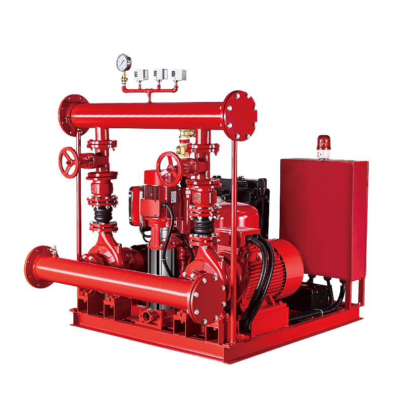 Fire Pump and System
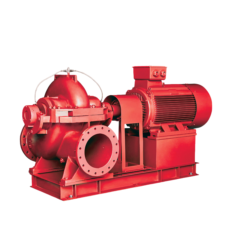 Split Case Pump
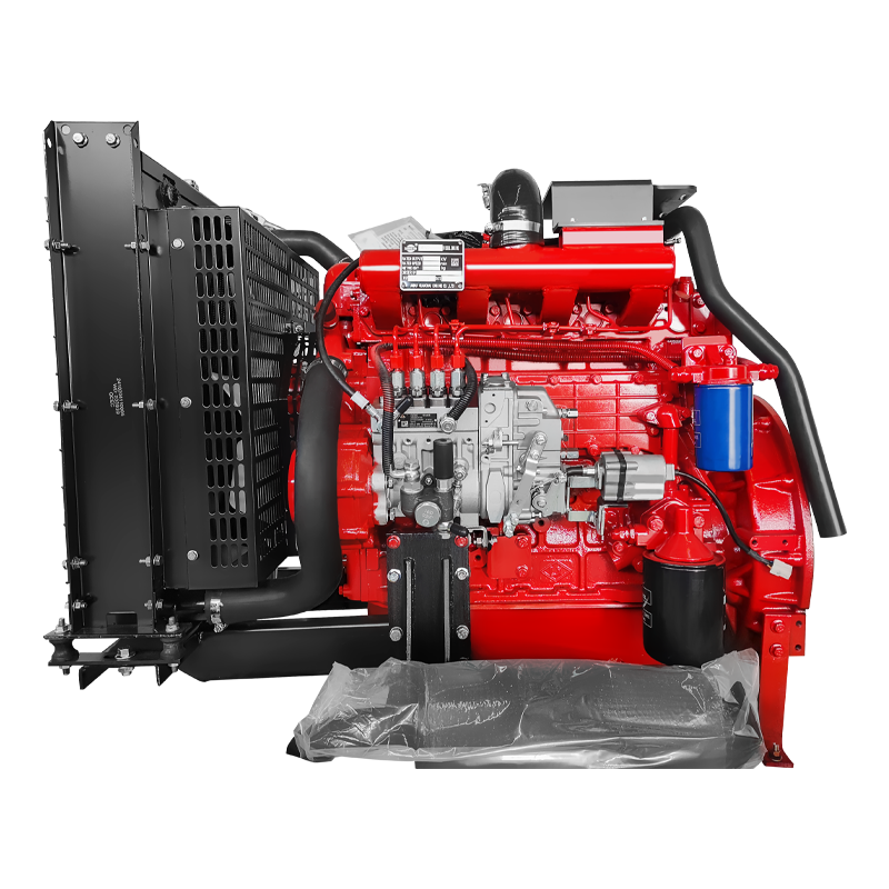 Engine and Pump
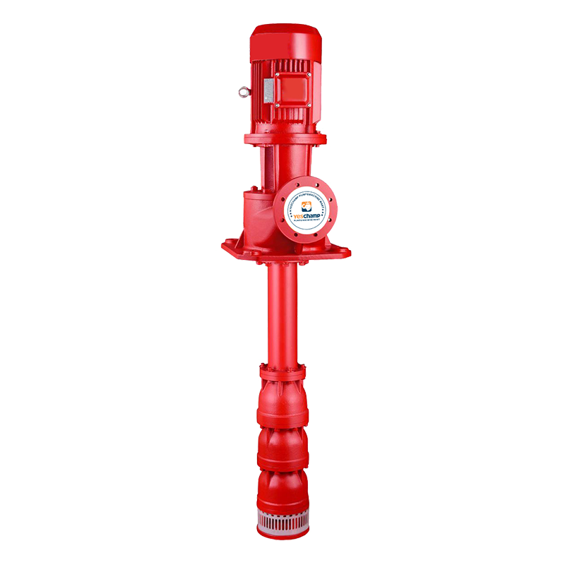 Long Shaft Pump
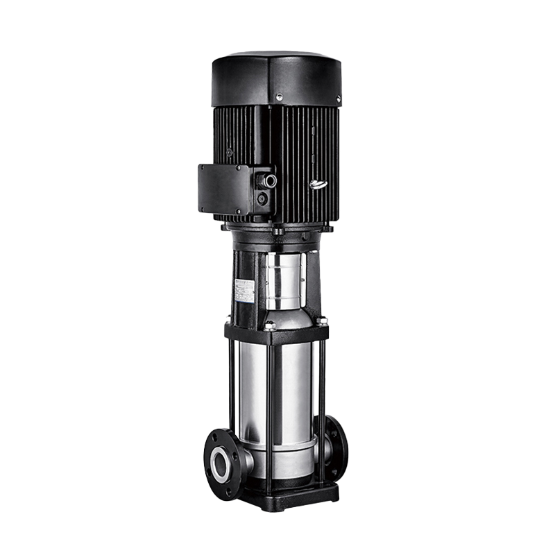 Multistage pump
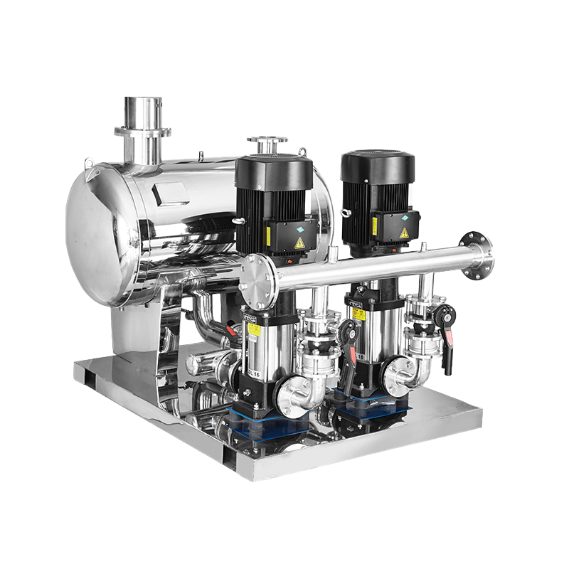 Water Supplier System
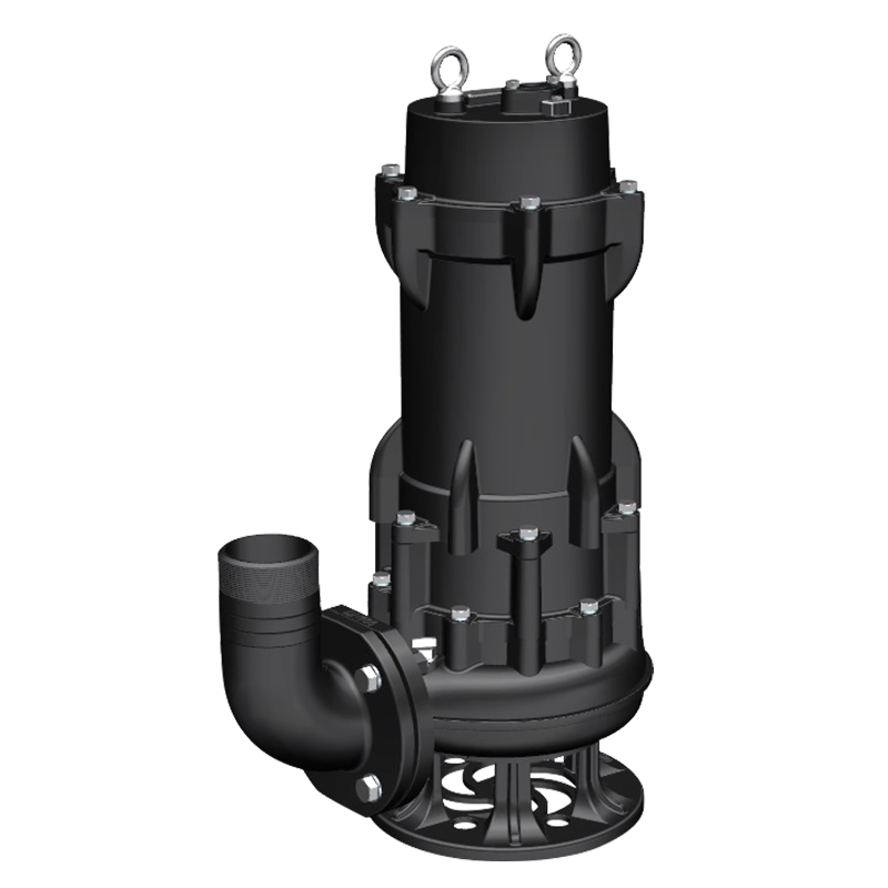 Sewage Pump
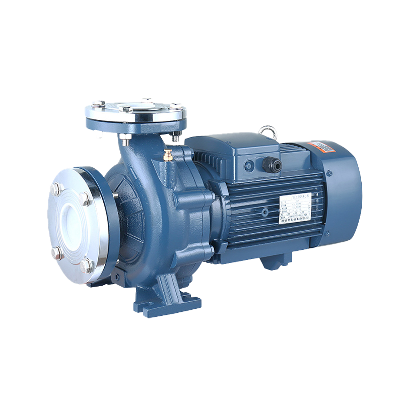 Industrial Pump
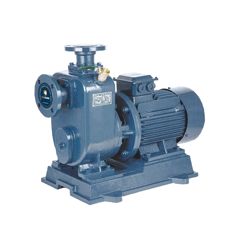 Self-Priming Pump
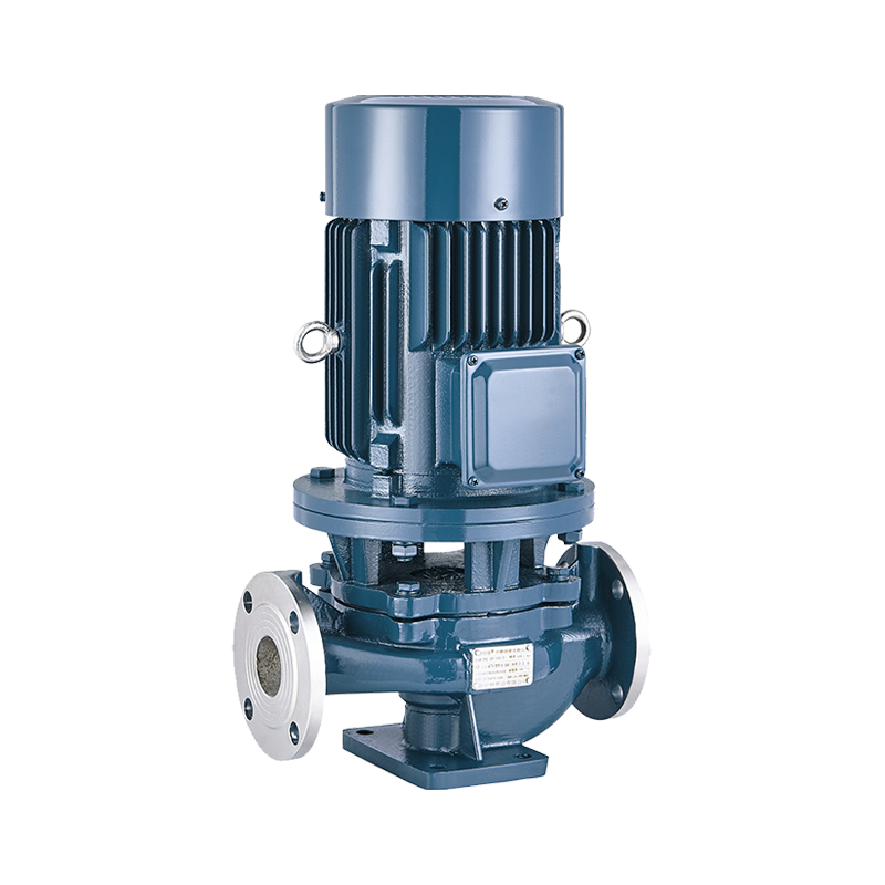 Inline Pump
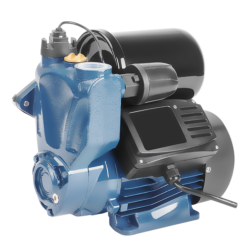 Domestic Pump
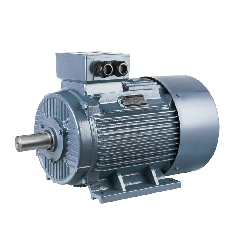 Electric Motor
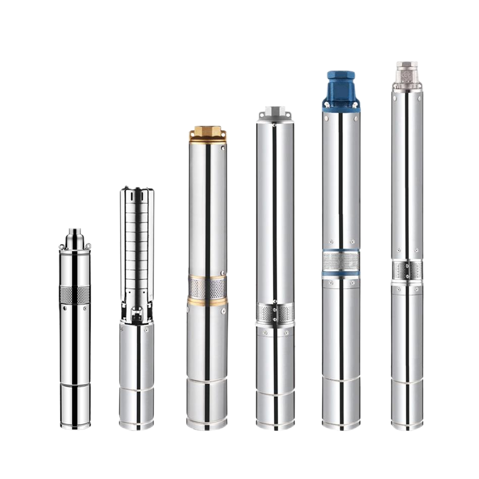 Borehole Pump
High-Flow Fire Protection: Split Case Fire Pump Selection & Engineering Guide
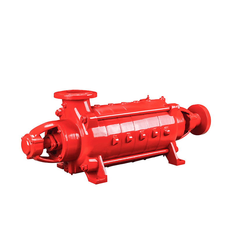
In high-rise commercial buildings, sprawling industrial parks, logistics warehouses, and municipal infrastructure, active fire suppression systems demand massive water delivery at stable, sustained pressures. The split case fire pump—specifically the horizontal double-suction split-case centrifugal pump—is the primary engineering solution for high-capacity fire water supply networks.
Engineered to meet rigorous industrial fire pump standards (such as ISO 9906, EN 12845, or GB 6245), split case fire pumps combine balanced double-suction hydraulics with rapid inline maintenance accessibility, ensuring dependable performance during critical emergencies.
1. Core Hydraulics: Why Split Case Pumps Excel in Fire Water Supply
Unlike single-suction pumps that draw water into one side of the impeller, a horizontal split case fire pump utilizes an axially split volute casing and a symmetrical double-entry impeller. This mechanical design provides three key operational advantages:
-
Balanced Axial Hydraulic Thrust: Water enters both sides of the double-suction impeller simultaneously. The opposing hydraulic forces cancel each other out, minimizing axial loads on the shaft and extending bearing life under continuous high-load operation.
-
Superior Cavitation Resistance (Low $\text{NPSHr}$): Dividing incoming flow across two impeller eyes reduces inlet fluid velocity by roughly 50%. This lowers the pump's Net Positive Suction Head Required ($\text{NPSHr}$), preventing destructive cavitation during peak flow demand.
-
Top-Cover Inline Maintenance: The pump casing splits horizontally along the shaft centerline. Maintenance technicians can unbolt and lift the upper casing half to inspect or replace the impeller, wear rings, and shaft seals without disconnecting suction/discharge piping or disturbing motor alignment.
2. Split Case vs. End Suction vs. Vertical Turbine Fire Pumps
Selecting the optimal fire pump geometry depends on required flow capacity, water reservoir elevation, and pump room space constraints:
| Engineering Parameter | Horizontal Split Case Fire Pump | End Suction Fire Pump | Vertical Turbine Fire Pump |
| Typical Flow Range | 100 $\text{m}^3/\text{h}$ to 1,200+ $\text{m}^3/\text{h}$ (440 – 5,300+ GPM) | 10 $\text{m}^3/\text{h}$ to 180 $\text{m}^3/\text{h}$ (45 – 790 GPM) | 50 $\text{m}^3/\text{h}$ to 1,200+ $\text{m}^3/\text{h}$ (220 – 5,300+ GPM) |
| Head / Pressure Range | 30 m to 180+ m (3 – 18+ Bar) | 25 m to 140 m (2.5 – 14 Bar) | 30 m to 250+ m (3 – 25+ Bar) |
| Suction Condition | Flooded / positive suction recommended | Flooded / positive suction recommended | Deep-well / negative suction lift (underground tanks, rivers) |
| Mechanical Footprint | Wide horizontal baseplate | Compact | Minimal floor area (requires vertical headroom) |
| Primary Applications | High-rises, industrial plants, logistics hubs, municipal fire mains | Small-to-medium commercial buildings, auxiliary booster loops | Underground fire cisterns, open reservoirs, coastal/river intakes |
3. Hydraulic Performance & System Reliability Features
Industrial split case fire pumps are engineered with flat-to-steadily-rising performance curves to prevent pipe over-pressurization at shutoff while maintaining strong residual pressure at maximum flow:
-
Non-Overloading Power Curve: Shaft power requirements remain within the driver's rated capacity across the entire operating curve, preventing electric motor tripping or diesel engine stalling during peak hydrant/sprinkler discharge.
-
High Hydraulic Efficiency: Precision-cast double volute and double-suction impeller passages deliver peak efficiencies up to 85% – 90%, reducing driver horsepower requirements and lowering total system cost.
-
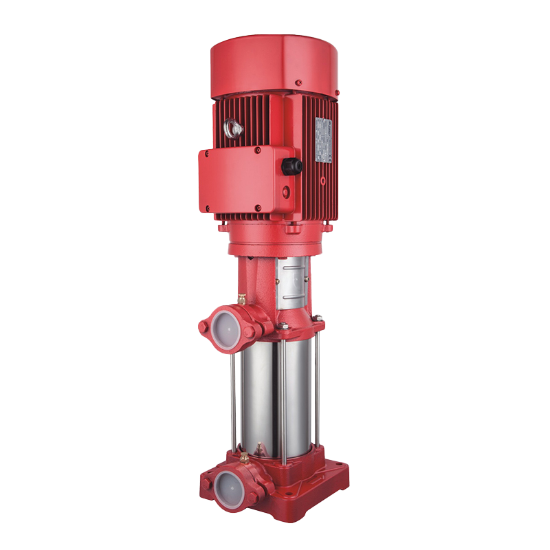
Automatic Pressure Stabilization: When paired with a vertical multistage jockey pump and pressure tank, the system maintains constant static network pressure and eliminates false main-pump starts caused by minor piping leaks.
4. Suction Piping & Installation Best Practices
Proper suction piping layout is critical to eliminating air pockets, vibration, and cavitation during emergency operation:
-
Straight Suction Pipe Run: Maintain a straight pipe length of at least 5 to 10 times the suction pipe diameter directly ahead of the pump inlet flange to ensure uniform flow distribution into both sides of the impeller.
-
Flat-on-Top Eccentric Reducers: Always install eccentric reducers with the flat side on top when transitioning from a larger suction header to the pump flange so air bubbles cannot accumulate at the crown of the pipe.
-
Avoid Parallel Suction Elbows: Do not install an elbow directly parallel to the pump shaft immediately before the suction nozzle, as uneven flow velocity can overload one side of the double-suction impeller.
-
Independent Pipe Supports: Support suction and discharge piping independently near the pump flanges so thermal expansion or water hammer loads are not transmitted to the pump casing.
5. Wetted Metallurgy & Drive Configurations
Because fire pumps spend most of their service life in standby mode before sudden full-speed activation, corrosion-resistant internal components are essential to prevent rotor seizure:
-
Pump Casing: Heavy-duty Cast Iron (HT250 / GG25) or Ductile Iron (QT450 / GGG40) with double-volute design on high-head models to balance radial forces.
-
Double-Suction Impeller: Cast Bronze (ZCuSn5Pb5Zn5 / CAC406) or AISI 304 / 316 Stainless Steel, dynamically balanced to ISO 1940 G6.3 for low-vibration operation.
-
Shaft & Shaft Sleeves: High-tensile AISI 420 (2Cr13) or AISI 304/316 Stainless Steel fitted with replaceable protective sleeves across the seal chamber.
-
Shaft Sealing: Heavy-duty gland packing (allowing controlled drip cooling) or cartridge mechanical seals (SiC/Carbon/EPDM) for zero-leakage clean environments.
-
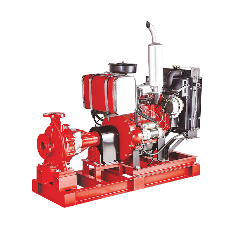
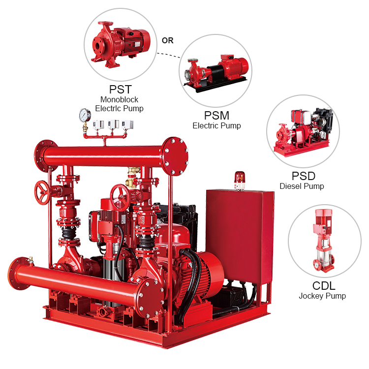
Flexible Drive Options: Available as standalone Electric Motor Driven, Diesel Engine Driven (complete with radiator/heat-exchanger cooling, fuel tank, and dual batteries), or turnkey E+D+J (Electric + Diesel + Jockey) Skid-Mounted Fire Pump Sets.
Partner with an Industrial Fire Pump Manufacturer
Specifying the right split case fire pump requires matching your project's flow rate ($Q$), total dynamic head ($H$), Net Positive Suction Head Available ($\text{NPSHa}$), and local fire code requirements.
Planning a commercial or industrial fire water supply project? Contact our engineering team today to request hydraulic performance curve sheets, 3D CAD installation drawings, or a customized skid quotation.
 5th Floor, Comprehensive Building No. 5, Dongqiao, Dong'an Village, Daxi Town,Wenling City,Zhejiang,China
 +86 576 86090666

 +86 18667600006
 +86 18667600006
 24 Hours Online
