 3D ROOM
 (0)
(0) English
 عربى
عربى
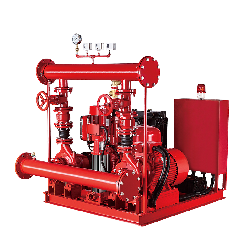 Fire Pump and System
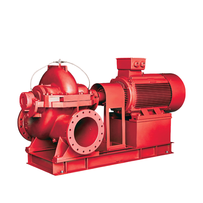 Split Case Pump
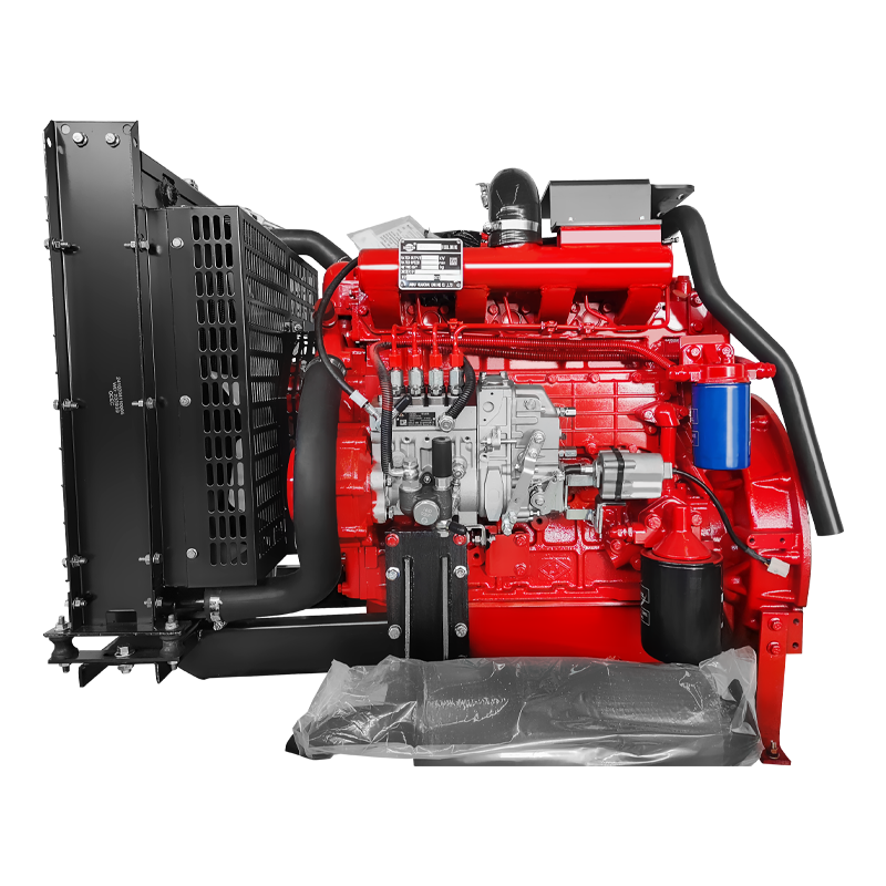 Engine and Pump
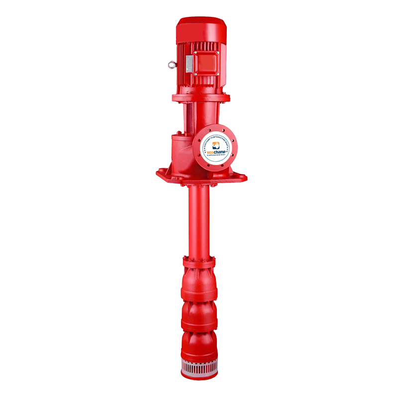 Long Shaft Pump
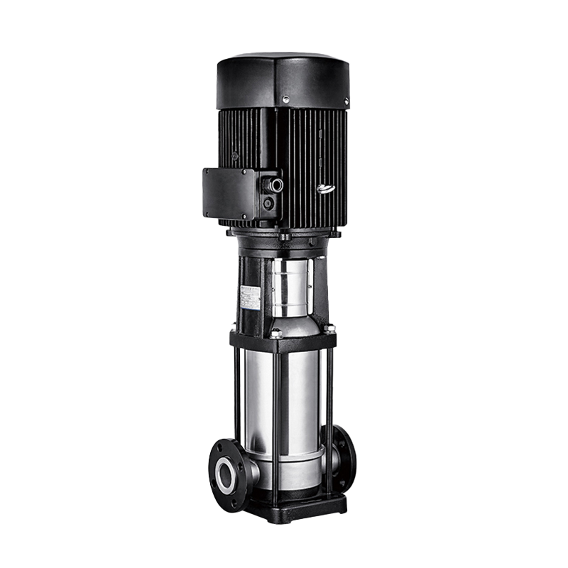 Multistage pump
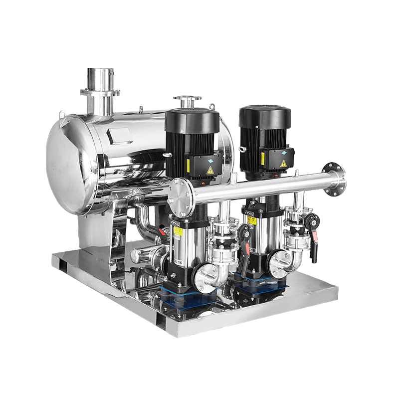 Water Supplier System
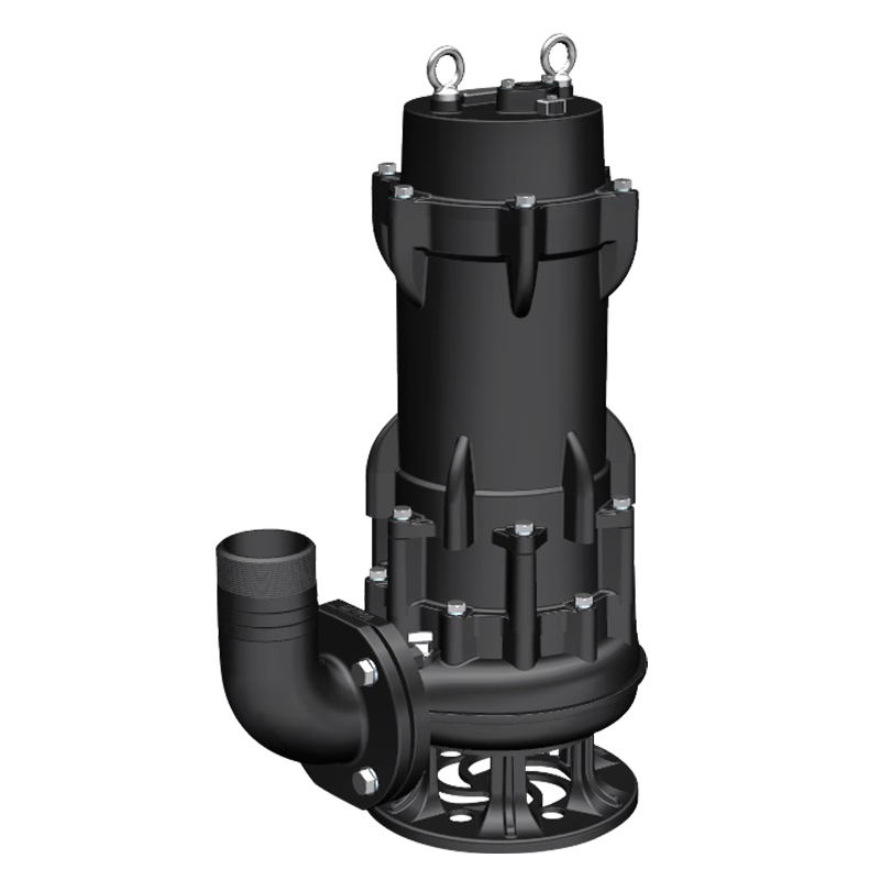 Sewage Pump
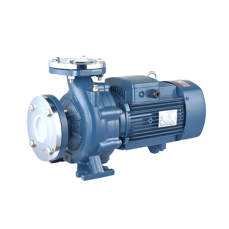 Industrial Pump
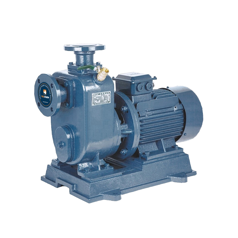 Self-Priming Pump
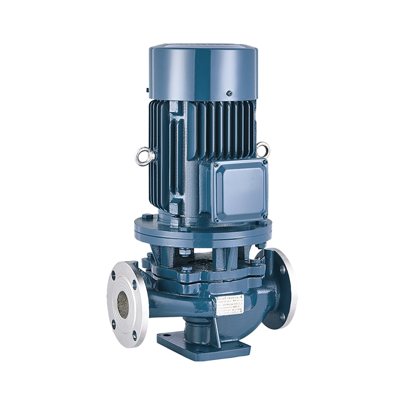 Inline Pump
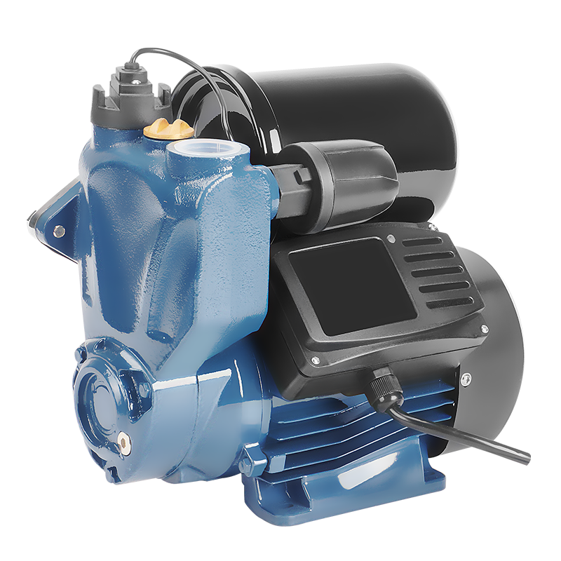 Domestic Pump
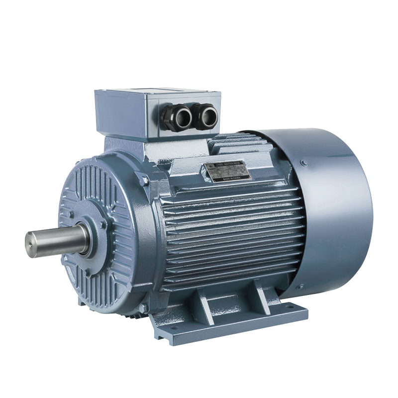 Electric Motor
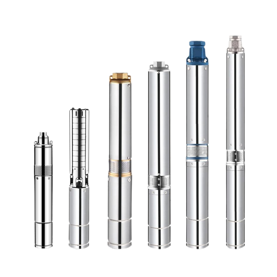 Borehole Pump
Complete Protection: Fire Pump System Design, Component & NFPA 20 Selection Guide
In commercial high-rises, sprawling logistics warehouses, and heavy industrial facilities, a building's fire sprinkler network is only as reliable as its water supply. When municipal water mains lack the flow capacity or static pressure needed during an emergency, an engineered Fire Pump System serves as the vital heart of active fire suppression.
Designed to deliver rapid, high-pressure water flow to sprinkler heads, standpipe hose valves, and deluge nozzles, modern fire pump packages must strictly comply with NFPA 20 (Standard for the Installation of Stationary Pumps for Fire Protection) and carry recognized UL Listed / FM Approved certifications.
1. Core Architecture: The 3 Main Components of a Fire Pump Set
A fully integrated fire pump station relies on three distinct pump assemblies operating within a synchronized piping header:
A. Main Fire Driver (Electric Motor or Diesel Engine)
-
Primary Role: High-volume, emergency water suppression during an active fire event.
-
Operation: Sized to meet 100% of system flow ($Q$) and Total Dynamic Head ($H$) requirements (typically ranging from 500 GPM to 5,000+ GPM).
-
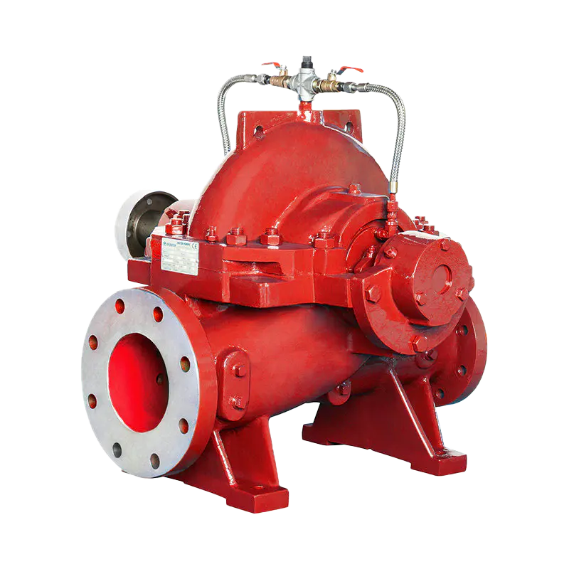
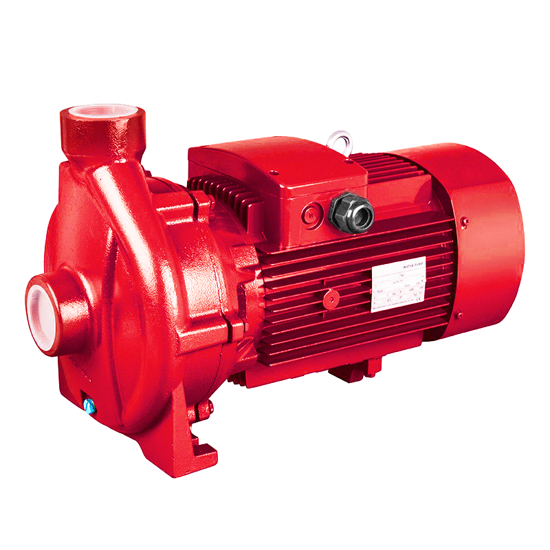
Configuration: Commonly paired with Horizontal Split-Case, End Suction, or Vertical Turbine pump geometries.
B. Secondary / Redundant Fire Driver (Diesel Engine Backup)
-
Primary Role: Failsafe backup during primary power grid failure.
-
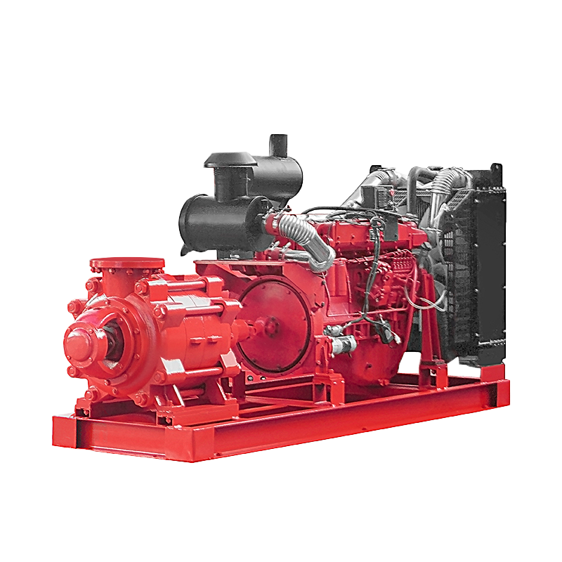
Operation: Fires frequently trigger power outages or short circuits. A dedicated diesel engine pump operates independently using on-site fuel storage and 24V battery cranking systems, guaranteeing uninterrupted water delivery.
C. Jockey Pump (Vertical Multistage Pump)
-
Primary Role: Static pressure maintenance & nuisance-start prevention.
-
Operation: Low-flow ($1\%\text{ to }3\%$ of main fire pump capacity), high-head vertical multistage pump. It automatically cycles on and off to compensate for minor system leaks or thermal expansion, keeping line pressure stable without triggering the main fire pumps.
2. Automatic Cascading Pressure Sequence
Fire pump systems operate automatically using a cascading pressure switch logic monitored by dedicated NEMA-rated controllers:
Static System Operating Pressure (e.g., 120 PSI)
   │
   ├── Drop to 110 PSI ──► [Jockey Pump STARTS] (Restores pressure to 120 PSI, then STOPS)
   │
   ├── Drop to 95 PSI  ──► [Primary Electric Fire Pump STARTS] (Requires MANUAL shutoff)
   │
   └── Drop to 80 PSI  ──► [Secondary Diesel Fire Pump STARTS] (Failsafe takeover / Grid loss)
NFPA 20 Compliance Rule: While jockey pumps cycle automatically on/off, main fire pumps (Electric & Diesel) must be started automatically via pressure drop but STOPPED MANUALLY at the control cabinet to ensure emergency personnel maintain total control on-site.
3. Selecting the Right Pump Configuration
Matching the correct pump architecture to building layout constraints is essential for performance and ease of maintenance:
| Fire Pump Geometry | Ideal Application Scenario | Primary Engineering Advantages |
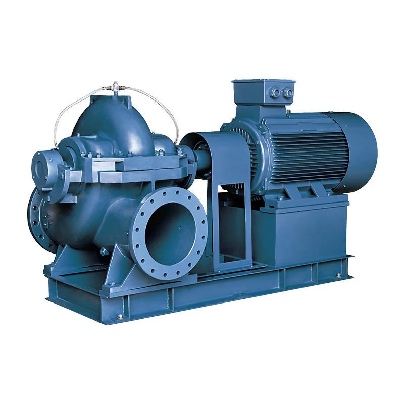
| Horizontal Split-Case (HSC) | Large commercial complexes, airports, waterworks | High flow capacity (up to 5,000+ GPM), dual bearings, easiest inline maintenance |
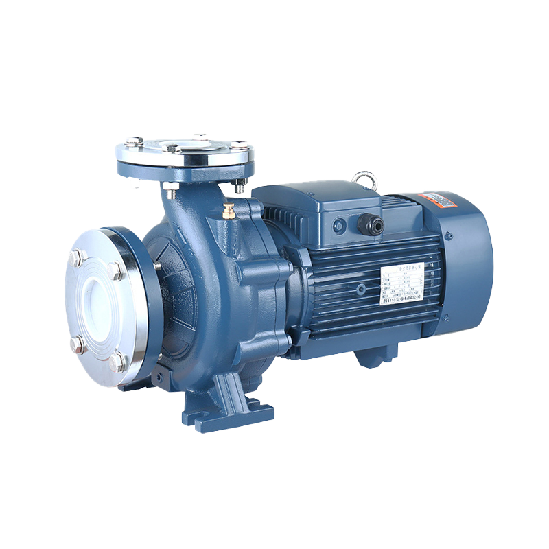
| End Suction Centrifugal | Small-to-medium commercial buildings, light hazard | Compact footprint, lower initial capital cost, simplified piping |
| Vertical Turbine | Deep wells, rivers, subterranean reservoirs | Draws water from static suction sources below pump grade (negative suction head) |
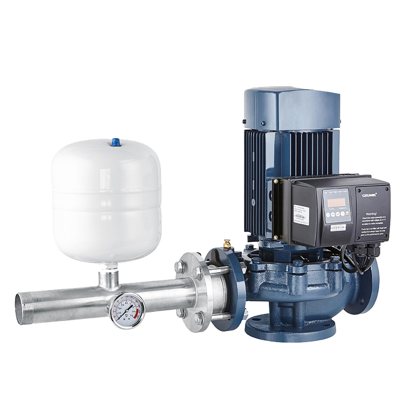
| Vertical In-Line | Space-constrained mechanical rooms | Direct inline installation, ultra-compact physical footprint |
4. Key Accessories in a Pre-Packaged Fire Skid
Sourcing a pre-engineered, factory-assembled fire pump package minimizes jobsite installation errors and streamlines field commissioning:
-
UL/FM Listed Control Cabinets: Separate auto-transfer switches and controllers equipped with digital pressure transducers and battery chargers.
-
NFPA 25 Test Header & Flow Meter Loop: Dedicated bypass loop with multi-port hose valves for performing mandatory annual 50%, 100%, and 150% capacity flow tests.
-
Suction & Discharge Headers: Pre-piped red-coated headers featuring OS&Y gate valves, check valves, and pressure relief valves.
Partner with an OEM Fire Protection Manufacturer
Whether you are designing a high-rise commercial fire loop, retrofitting an industrial logistics park, or preparing a B2B tender submission, specifying compliant equipment ensures full life-safety reliability.
Ready to secure your property's fire protection infrastructure? Contact an authorized fire pump engineering specialist today to request CAD dimensional blueprints, hydraulic performance curves, or a direct commercial price quotation.
 5th Floor, Comprehensive Building No. 5, Dongqiao, Dong'an Village, Daxi Town,Wenling City,Zhejiang,China
 +86 576 86090666
 +86 18667600006
 +86 18667600006
 24 Hours Online